
FIGURE 1. Northeast corner of the chiller plant, showing the 48-in. primary chilled water (PCHW) supply piping exiting the pipe tunnel.
Miami International Airport (MIA) is among the busiest airports in the world. With over 80 airlines providing service to approximately 150 destinations around the globe, MIA served almost 30 million passengers and moved over three million tons of freight in 2003. The airport is undertaking a $4.8 billion capital improvement program, including expanded terminals and concourses, which will add approximately 2.7 million sq ft of new areas to approximately 4.7 million sq ft of existing space; improvements to airside facilities; new cargo build-ings, which will add 3.3 million sq ft of handling and storage capacity; and improved ground transportation systems.
The program also includes a $48.4 million expansion of the 7,500-ton Central Chiller Plant East for the Miami-Dade Aviation Department. The capacity of the new central chiller plant will exceed 23,100 tons of cooling, placing it on a par with the largest chiller plants in the country - such as those that cool the Pentagon and NASA.
Central Chiller Plant East, located prominently on Central Boulevard at the entrance to the airport, was designed and engineered by Wolfberg, Alvarez & Partners of Miami, and constructed by general contractor Poole and Kent Company of Florida, an EMCOR Group company. Completed in 1989, the original 10-story structure features an extensive use of glass on the white concrete and ceramic tile façade, enabling the public to view the interior space and equipment. The building was cited in 1991 by the Florida Concrete and Products Association as among the "Out-standing Concrete Structures in Florida." Equipment consists of three York Turbo Master 2,500-ton centrifugal chillers, three 2,500-ton cooling towers, and support systems.
Expansion of Existing Plant
Commencing September 14, 2001, the first phase of the equipment expansion of Central Chiller Plant East involved the addition of two York model YK MaxE™ 1,800-ton, open-drive centrifugal chillers equipped with totally enclosed water cooled motors, environmentally safe R-134a refrigerant, associated piping and electrical service, reconditioning of the three existing chillers, and rebuilding and increasing the capacity of the three existing cooling towers to 3,600 tons each to support the additional chillers.As part of the plant upgrade, Wolfberg, Alvarez & Partners designed a retrofit of the condenser water sys-tems, providing solids separators and a condenser brush cleaning system to improve the quality of the condenser water and reduce fouling. The cooling towers were rebuilt using field-erected, polyvinyl chloride (PVC) fill surrounded by a masonry shell, increasing cooling capacity by more than 42%. Construction was staged to ensure the existing plant was maintained in continuous service, with only one chiller and cooling tower taken offline at a time.
The chiller and cooling tower upgrade work was completed by March 2002, in advance of the heavy summer cooling loads. The first phase was completed on schedule September 14, 2002.

FIGURE 2. The chilled water pumps and piping.
Building Addition and Equipment Expansion
The second and most extensive phase of the project involved construction of a 59,000-sq-ft addition to Central Chiller Plant East to house three new York Titan™ 4,000-ton 5 kV open-drive centrifugal chillers equipped with totally enclosed water cooled motors, R-134a refrigerant, four new field-erected cooling towers comprising PVC fill surrounded by a masonry shell, and associated piping and electrical service. This phase of the project also included installation of 3,500 linear ft of new 24-in. chilled water piping on new pipe supports on the terminal roofs to facilitate distribution of chilled water.The addition, which increased the area of Chiller Plant East by approximately 160%, includes space for additional chillers and a cooling tower build-out. The chillers are provided with sound enclosures in the motor/compressor section to achieve a maximum noise level of no more than 85 dBa. The chillers and major components, such as pumps and cooling towers, have a Rockwell Automation Entek® vibration monitoring system to lengthen the service life of the equipment. The hydronic pumping system consists of primary, secondary, and tertiary systems. The chiller loop is designed with constant flow while the transport and tertiary systems are designed with VFDs to obtain variable flow. This important design feature will reduce the operating costs of the plant.
New BMS
The design also includes an extensive BMS, which monitors and optimizes the functioning of vital equipment. The BMS components include five distributed Honeywell Excel Plus™ DDC controllers with Openlink Modbus interfaces. The Openlink Modbus interfaces monitor information directly from the York chillers, Danfoss Graham VFDs, and the Entek vibration monitoring system.The distributed DDC controllers select and sequence the chillers, pumps, and cooling towers, and also provides sequence control for the TES plant. Additionally, the DDC monitors critical information from the refrigerant monitoring system and the chemical treatment system. The cooling towers are designed with Danfoss Graham VFDs to conserve energy and achieve optimum control.
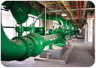
FIGURE 3. The condenser water pump on an inertia base with condenser water piping connected.
Solving Complex Construction Challenges
To expedite Phase 2, while Phase 1 of the project was still in progress, Poole and Kent commenced above ground structural work and the submittal and approval process for the new 4,000-ton chillers. The project was logistically complicated by the presence of three adjacent construction projects, including a roadway extension project immediately to the south and a central toll collection plaza project to the north, which limited crane access to the chiller plant construction site.Moreover, the 11-month lead-time on delivery of the 4,000-ton chillers necessitated an innovative installa-tion process. Each chiller was delivered on flatbed trucks in three primary parts: the motor/compressor package, evaporator barrel, and the condenser barrel. Assembled, each chiller weighs over 280,000 lb. Ordinarily, the equipment is assembled and installed on pads using a conventional stationary crane, and then a structure is built over it. In this case, the long lead-time on delivery of the chillers meant that the structure had to be built first to maintain the project schedule. This required use of a mobile low-head, low-height crane to transport the components into the building and set them in place.
Installation of 48-in. dia pipes 25 ft above the finished floor posed another construction challenge, which was solved using electric hoists rather than conventional manual chain hoists, reducing the time taken to position each pipe from approximately 45 min to 10 min.
TES
The engineers designed the plant with a 12,000 ton-hour TES system to reduce peak kilowatt demand and pro-vide redundancy. The system, which is capable of providing 1,500 instantaneous tons of discharge, comprises two York model YS open drive rotary screw chillers that use a water-glycol mixture and six 40-ft-by-11-ft ice storage tanks, containing a total of 792,000 ice balls. These tanks are located on the mezzanine of the building with the ice chillers.Installation was accomplished by leaving the south wall of the building open from the mezzanine to the third level and using a crane to slide the tanks horizontally into place. Once each tank was installed and insulated, the ice balls were loaded using a chute fed through an opening cut in the roof.
The new 4,000-ton chillers were started up to provide cooling for the airport, and MIA's existing chiller plant was shut down and drained this past February.
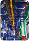
FIGURE 4. Third-level PCHW pumps and Piping.
Seamless Integration
In the third and final phase of the project, the chilled water systems for the existing and new equipment in Central Chiller Plant East were tied together through the chilled water distribution network to provide optimal flexibility in the overall operation of the A/C system at the airport. The BMS was extended to cover the new equipment.A building network adapter, in conjunction with the owner's LAN, provides a communication path from the chiller plant's distributed DDC to the state-of-the-art Honeywell Enterprise Building Integrator (EBI) Building Manager. The EBI collects and stores data from the chiller plant and also provides critical chilled water sys-tem pressure information to the chiller plant from select locations in the main terminal building.
There are three station graphical operator interfaces in the chiller plant; two are located in the second floor plant control room, and a single touch-screen station is located on the main level of the plant. All stations pro-vide the ability to view and respond to alarms, schedule equipment operation, adjust operating sequences, analyze data, and constantly monitor an extensive list of vital functions and maintenance-related activities. The Entek vibration monitoring system monitors chillers, pumps, cooling towers, and other components of the chiller plant.
With ultimate expansion capability to 40,000 tons of refrigeration, Central Chiller Plant East will support the continued growth and efficient operation of Miami International Airport well into the future.
MacClugage is project executive for Poole and Kent, a Miami, Florida-based mechanical contractor.
Strickland is manager, business development for Poole and Kent (Miami).
Poole and Kent Company of Florida is a subsidiary of EMCOR Group, Inc., a Fortune 500® leader in mechani-cal and electrical construction, energy infrastructure, and facilities services for a diverse range of businesses globally.
