Today's boiler plant is equipped with electronic (digital or analog) controls for each boiler to control flame monitoring, fuel and air valves, and startup and shutdown sequences. Further, the plant is equipped with a separate microprocessor, the plant master, which coordinates all boilers and equipment while recording data and providing a communications link. The modern plant master controller may be a proprietary combination of hardware and software specially designed for boilers or it may be a general-purpose industrial controller programmed for the needs of the plant.
Flame Loss: More Than Just the Cold Shoulder
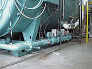
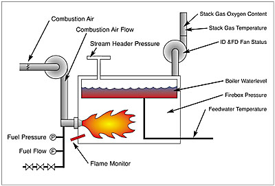
Individual boilers have always had safety circuits to monitor the presence of the combustion flame and ensure that the fuel supply is completely shut off in the event of a flame failure. Redundant automatic valves in the gas supply piping or fuel train (Figure 1) shut off the fuel supply in the event of a boiler trip. Without such a system, the boiler could fill with combustible fuel and present the danger of explosion when the burner is restarted. Most boiler safety controls use a photoelectric sensor to confirm the presence of a stable, efficiently burning flame. If this flame is lost or becomes unstable for any reason, the fuel is shut off and an alarm is sounded.In addition to flame loss or instability, the following can also cause a boiler shutdown (Figure 2):
- High steam pressure;
- Low or unstable fuel pressure;
- Low or high boiler water level;
- Low or high feed water temperature;
- Unstable boiler water level (foaming);
- Low or unstable combustion airflow;
- Incorrect combustion air damper position;
- Incorrect combustion air fan status;
- High, low, or unstable firebox pressure;
- High or low stack gas temperature; and
- High or low stack gas oxygen content.
In the case of a boiler safety trip in the fully automated boiler plant, the plant master controller takes over to increase the burn rate of other boilers or bring new boilers on-line, as required, to meet the plant load. The use of the plant master controller is not necessarily intended to replace the boiler operator, but it gives the operator time to safely determine the cause of the boiler trip and automatically transmits an alarm to others if required.
Clearing the Air About Reignition
Central plant steam boilers typically produce steam at pressures upwards of 15 psig and are considered high-pressure steam boilers. Boilers rated at over 15 psig are labeled by the American Society of Mechanical Engineers (ASME) and must conform to required standards of material and construction. Pressures may run to 100 psig in a typical community steam distribution system and up to several hundred psig if the steam is used in a steam turbine cogeneration system. The additional pressure is required to overcome the pressure drop of the distribution system. Steam at these pressures is up to 200¿F hotter than the steam used in single buildings heated with dedicated boilers. This means that the interior of these large central boilers is at least that much hotter than their smaller counterparts.The real danger that lies in the loss of burner flame is the potential of an explosion, and the higher internal temperatures in large central plant boilers aggravate this danger. An explosion can be caused by either the burner attempting to relight the flame in a furnace full of combustibles or by the fuel-air mixture coming into contact with a hot surface or hot particle in the boiler.
To guard against either event, the fuel source must be shut off and kept off until reset by the operator at the boiler. The other controls on the boiler see that the water level is maintained as the unit cools and also that combustion air is circulated through the boiler to dilute the remaining fuel-air mixture below the threshold of combustion. This dilution or purging of the boiler combustion space must continue until the boiler is cooled safely below the fuel combustion temperature.
When purging is complete, controls confirm that fuel pressure is sufficient for burning. The controls then turn on the combustion air fans, monitor the air volume, and open the fuel valves in conjunction with energizing the ignition device.
All of the above procedures are controlled by the local boiler controls. Whereas older control systems were based on a combination of pneumatics and electric relays, their modern counterparts are either analog or digital electronic circuits. The newer, microprocessor-based controls are faster and monitor more elements of boiler operation than their electromechanical predecessors and improve the safety of the plant.
Enter the Plant Master
After the boiler trip, the plant master controller has brought the other boilers to bear on the absence of the tripped unit. As the boiler is brought back on-line, the master controller reduces the firing rate of the remaining boilers and orders one or more shut down as required to achieve the best overall efficiency from the group. Boiler shut- down is done slowly, according to a preplanned program, to minimize the thermal shock to the boiler and reduce eventual failures due to metal fatigue.All the while this is happening, the plant master records all of the shutdowns, start-ups, and burn levels of all the units as well as the original trip. It also makes a continuous record of all of the safety parameters listed above.
In addition to measuring and recording, the plant master microprocessor can be programmed to continuously calculate the overall thermal efficiency of the plant. It does this by totalizing the steam output of the plant and dividing by the total heat value of the fuel into the boilers per unit time. This provides a measure of the efficiency of the plant, expressed as pounds of steam per Btu of fuel consumed. Over the billing period this is averaged and converted to the dollar cost per 1,000 lb of steam, which is used for billing the users on the distribution system.
So Why the Failure?
A boiler shutdown can result from a very brief abnormality in any one of a dozen variables. Modern microprocessor controls must be able to instantly list the faults that led to the failure in order to allow the plant staff to address the problem and ensure the boiler is reliable and safe to restart. Better plant master systems may even include software that will diagnose complex combinations of factors and present the most likely causes of the burner failure.The ability of modern electronic controls to monitor boiler conditions many times a second is critical in analyzing the myriad of rapidly changing factors in a boiler shutdown. The modern electronic controller will even check itself and report such subtle malfunctions as a faulty plug or an intermittent high-resistance wiring terminal.
Note that less expensive controllers may provide fault diagnosis in the form of cryptic codes that operators must memorize or decode in the event of a failure. Controllers that read out faults in English will provide more reliable assistance in an emergency.
Stack Gas Savings
When converting to microprocessor controls, don't forget stack gas monitoring to optimize boiler fuel efficiency. Several types of stack gas monitoring are available for efficiency and for conforming to regulatory requirements. For larger boilers, continuous emissions monitoring (CEM) may be required by federal or local governments. This type of stack gas monitoring is usually based on mass spectrometry and has little to do with optimizing fuel efficiency.The most common stack gas system aimed at improving fuel economy is oxygen trim. An oxygen trim system continuously monitors the stack gas for oxygen content and adjusts the burner fuel/air ratio accordingly. The oxygen trim system does not take the place of the standard fuel/air controls; it only makes slight adjustments to those controls.
The trim system adjusts the fuel/air mixture to a preprogrammed minimum acceptable stack gas oxygen content. This, in theory, represents the most efficient burn because the lowest possible amount of combustion air is being heated and exhausted. The level of oxygen in the stack gas never gets to zero because no boiler has yet achieved a perfect burn.
Switching to Lower Costs
Fuel switching and fuel mixing is another important strategy in lowering plant energy costs. In large central plant boilers, each boiler may have several burners. If the burners in the plant are capable of burning several different fuels, say, fuel oil, natural gas, and propane, this gives the operating staff an opportunity to determine which is the most economical at a given time.For example, most boiler plants can save money immediately on their fuel supply costs by changing from a firm fuel supply contract to an interruptible contract. The interruptible contract specifies that the utility supplier may restrict or curtail the plant's daily usage, usually with 24 to 72 hrs advance notice. This helps the utility reduce the number and size of expensive pipelines it must install and maintain. Note, however, that the customer saves money based on the terms of the contract even if the subject fuel is never curtailed.
In the event of a curtailment, the plant master controller can be programmed to limit the quantity of the curtailed fuel to the contracted amount. Moreover, the controller will plan ahead and shut off the appropriate burners slowly to allow the boiler to cool slowly and minimize thermal stress in the unit. Alternatively, the plant master can base load the subject burners so that their consumption of the curtailed fuel falls just short of the contracted amount at day's end. This base loaded burn can continue indefinitely and stay within the contracted curtailed amount.
If the curtailed burners are base loaded, the most efficient burners using alternate fuels can be swing loaded to provide the remaining required capacity. If the curtailment is severe, the swing-loaded burners may burn considerable fuel and reserves need to be arranged beforehand.
Purchasing Fuel on the Run
It is standard procedure to purchase as much reserve fuel as possible in the summer months or other times of the year when the price is low. However, in the next few years the country is going to see the increased use of time-of-day scheduling for pricing utilities. How does this work in the modern boiler plant? It's easy with a programmable plant master.As when the user is operating on a curtailed fuel schedule, the plant master system is programmed to base load the burners using the subject fuel. However, the base loaded schedule is not uniform, but follows a programmed curve throughout a 24-hr day. For example, if the local utility found itself strapped for capacity when its customers were all starting up in the morning, say from 6 a.m. to 9 a.m., it might be willing to provide a substantial rate reduction to a customer willing to curtail during those hours.
To accomplish this, the plant master is programmed to reduce the firing rate at those hours at those boilers using the subject fuel. The boilers have to stay hot, so the firing rate probably should not be reduced below about 20%. But this should still be a significant benefit to the local utility. The remaining boilers are then swing loaded to pick up the required load with alternate fuels and the plant master automatically adjusts their burn rates to the optimum.
Communicate and Prosper
Although many boiler plants are manned 24 hrs a day, the increased use of redundant safety controls and improved communications equipment are allowing increased unmanned operation. As described above, the programmable plant master can be used to automatically regulate boiler burn rates with regard to several factors to achieve the best overall efficiency and lowest overall costs. If that controller is connected to the outside world by either modem or the campus local area network (LAN), that fuel consumption information is available to those outside the plant as well.This access to information could be useful for several reasons. For example, if a large enterprise chose to have its utility purchasing done through its purchasing office rather than the central plant, it would be handy for the purchasing office to have instant access to "real time" fuel consumption data. This is especially true if the enterprise is operating with an interruptible contract. If the utility calls with questions regarding complex contract issues, the purchasing agent can display a graph of consumption on his desktop PC to help sort out the issues.
Figure 3 shows a simple method of connecting several boilers with electronic controls to a central workstation that is, in turn, enabled with telephone access via a modem. This plant may be equipped with a plant master controller or it may simply have several unitary controllers networked together to a workstation. The communication provided by the modem is much slower than that provided by the direct data network connection (see sidebar). But it may provide an economically feasible first step towards company-wide visibility.
Access to the Internet provides even more power for the accurate analysis of fuel consumption patterns. Not only can the purchasing agent and chief operating engineer both access utility burn rates from their home computer, but also the utility itself can monitor the use of the regulated fuel. This not only enhances communication, but also can actually shift responsibility onto the shoulders of the utility and away from the owner.
Figure 4 shows how a central plant master controller can be connected to the enterprise LAN and then to the Internet via the LAN/Internet server. This provides the fast data transfer that is required for the real-time display of graphical fuel consumption data.
Although safety issues are of primary importance in the operation of any boiler plant, eventually Internet access will allow the utility provider to directly control the fuel mix at the boilers. This will allow the plant load to be met at the lowest possible cost to the enterprise considering all facets of the fuel cost including product, infrastructure, and delivery.
Maintenance and Operations Benefits
Providing microprocessor-based control offers several benefits to the plant operations staff. Probably the most important benefit is the ability to remotely check on plant operation and diagnose faults. For example, in the event of a boiler trip on a weekend or holiday, the plant operator on duty might want to compare notes with a supervisor before restarting a boiler. If the plant is Internet enabled, the supervisor can quickly access all plant parameters at home and discuss the pertinent issues with the operator.In the same manner, the plant staff can share ideas with the installing contractor or the equipment vendor over the Internet. This provides ongoing training for the O&M staff as well as protecting warranty provisions for the plant controls. The staff can act on the instructions of the installer or the installer can travel to the site and do the work with his/her own staff.
Finally, automating the plant has the potential of freeing the plant staff to do work outside of the plant, leaving the plant unattended. Although many states and localities require high-pressure boilers to be attended, many plants are moving to a system of roving operators. These operators perform a variety of maintenance operations on the campus but can respond quickly to a boiler trip.
As wireless Internet becomes a reality, remote operators can see the status of dozens of plant parameters without even being in the building.
Installation Tips
When converting to electronic digital or analog controls, keep the following tips in mind:
- Avoid the installation of any electronic analog or digital controller on a vibrating surface such as a pump rack or fan. Vibrations will loosen all connections in time and provide hard-to-diagnose high-resistance connections.
- Discuss the ambient conditions of the central plant with the manufacturer's application engineer and confirm that they are within the tolerances of the controller circuitry.
- Do not install the control chassis on a cold surface in a warm, humid boiler room. Moisture will condense in the enclosure and eventually cause failure.
- Be aware that all electronic circuits can be damaged by poor power quality. If the plant must operate on emergency power, ensure that power conditioners are in place to protect the controls from the bump that will occur when the generator comes on-line.
- If the controller is to communicate over the local area data network (LAN), confirm that the protocol used by the controller will not interfere with other information and that router ports and addresses are available.
- Discuss the new controls with the plant insurance underwriter and specify the approvals and acceptances that the underwriter requires.
- Note that boilers over 1 MMBtuh input may require either state or federal licenses or both and will probably require continuous emissions monitoring.
By following these tips and working with qualified vendors and installers, your boiler plant can reap the savings of more efficient control for years to come. ES
EDITOR'S NOTE: Some of the images/figures associated with this article do not transfer to the Internet. To review the figures, please refer to the print version of this issue.
Modernize your boilers with microprocessors for:
- Safer boiler operation;
- Controlling more plant variables;
- Recording more plant variables;
- More efficient boiler operation;
- Remote visibility for fuel purchasing;
- Remote visibility for fault diagnosis;
- Maintenance staff flexibility;
- Improved documentation; and
- Scheduled maintenance


