
Taconic Hills Central School District had a 25-year record for defeated construction referendums. As a result, all of the district's facilities were extremely antiquated and in disrepair.
With a growing student population, the existing buildings needed to be completely gutted and large additions added to each building. The existing buildings were also scattered all around the district; as a result, many students had more than an hour-long bus ride each way. The design team had to become creative to solve this problem. After months of detailed analysis, the team decided that a single, new, centrally located facility would be the answer.
Picking Up The Designing Pace
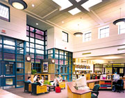
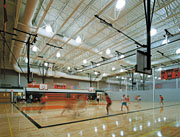
A single, standalone K-12 building became the most economical solution. A beautiful, 53-acre site was selected and purchased, and the design team went to work. This building would need to be the crux of the district's school facility program for years to come. Multiple building layouts were generated for evaluation. The new site had to accommodate the building, several athletic fields, a track, tennis courts, elementary playgrounds, a concession stand, a new bus garage, and parking for an entire district. The main building would house classrooms, two cafeterias and kitchens, computer rooms, music rooms, media centers, three gymnasiums, a natatorium, an auditorium, industrial arts rooms, document storage rooms, and offices.The building design work quickly became a fast-paced adventure, with a total design time of only nine months for a 350,000-sq-ft project. The engineers and architect had to work diligently to seamlessly integrate all of the engineering systems into the building. Daily design conferences were the norm and the coffee pot never stopped perking.
All of the engineering systems were designed with flexibility and future growth in mind. The utilities that feed the building were the first hurdle. The site was remote from any major town and required the use of well water for domestic and fire protection systems. A series of deep wells were drilled and tested for quantity and quality.
The water system employs a 40,000-gal underground, lined concrete tank with an architecturally consistent pump house constructed on top of the tank that houses the fire pump and water treatment systems. Since the building is only partially sprinklered, the decision was made to use a small diesel fire pump. The main underground water tank was also used as a chlorine contact tank and has worked flawlessly. The sanitary waste is pumped from the building to remote septic tanks and leach field along the perimeter of the site.
The closest power connection location to which the site could hook up is almost a half a mile away, so the electrical engineers designed a 34.5-kV underground service to feed a pair of pad-mounted transformers. Two transformers were used to offer some redundancy to ensure reliable operation of the service. The facility was also designated an emergency disaster shelter and a large diesel emergency generator was installed. The generator can power all of the emergency lighting, data systems, control systems, the boiler plant, one complete cafeteria (including all the coolers), and one gymnasium.
Inside The Mechanical Room
The design team then focused on the building itself. The hvac system utilizes hot water and chilled water for heating and cooling. The boiler plant uses three 300-hp, four-pass oil-fired boilers (one boiler serves as standby).The district had been using No. 4 oil in its old facilities because it was purchased at bulk rates and was inexpensive, but it was agreed upon that No. 2 fuel oil was less problematic and would actually help reduce some maintenance costs. The fuel oil is stored in two 30,000-gal, double-wall, underground, fiberglass fuel tanks that are adjacent to the main mechanical room. This quantity of fuel supplies the building for an average winter month.
Since only part of the building is air conditioned, a pair of 250-ton air cooled screw chillers were selected over water cooled chillers because of their ease of maintenance. Most school districts shy away from open cooling towers and water treatment.
The chilled water mains, which loop around the core of the building, were upsized to cool the entire building. This allows for an easy future air conditioning conversion of all the classrooms if the state mandates year-round school. Both the chilled and hot water secondary pumps use variable-speed drives (vsd's) to help match the flow with the actual load and conserve pump energy. Large, vertical in-line pumps from Armstrong (Three Rivers, MI) were used because of their small footprint. Split-coupled, vertical in-line pumps that allow the mechanical seals on the pumps to be replaced without removing the motor were specified. The seals on a 150-hp pump can be changed in less than an hour.
Ventilation: A Principal Concern
The typical classroom is heated and ventilated with a Trane (LaCrosse, WI) console unit ventilator. Horizontal ducted unit ventilators were used in acoustically sensitive spaces or where cabinetry precluded the use of a console unit.During occupied mode the unit ventilators can use up to 100% outside air for ventilation and economizer cooling. Ducted relief systems for the classrooms use vsd's on the fan that track the outside air damper position on the unit ventilators. This allows the relief fan cfm to match the unit ventilator outside air cfm. The configuration maximizes the system's ventilation effectiveness and minimizes the relief fan's energy consumption. All of the large, single-zone rooms such as the atriums, media centers, and auditorium, use constant volume air-handling units (AHUs).
The office areas are served with variable-air volume (vav) AHUs. All of the AHUs, constant volume and vav, are equipped with minimum outside airflow measuring/modulating damper stations. These devices allow for continuous monitoring of outside airflow to ensure proper ventilation. The AHUs are also equipped with an airside economizer to help improve the building's IAQ and keep those chillers off-line as much as possible.
Both waterside and airside heat recovery systems were analyzed to determine their associated payback periods. The payback periods were long because of the building's large amount of square footage and a complete building heat recovery system was impractical. An analysis actually showed that most classrooms, loaded with 30 students, a few computers, and lights, required economizer cooling during 30 degrees to 40 degrees F weather.
The building has a total of 170 unit ventilators and 12 large AHUs. The design team was very concerned about freeze protection for all of the coils. To conserve energy all of the coils and terminal devices are equipped with two-way modulating control valves to help maximize pump energy savings. Even with freezestats, if the temperature control system malfunctioned and multiple coils froze, the school could be shut down for an extended period.
The owner was used to operating one- and two-pipe steam systems with unit ventilators equipped with face and bypass control. The team decided to fill the hot water system with a propylene glycol solution to help prevent potential coil freezeups. This gave the owner more comfort than relying on freezestats for protection. The owner has the option to remove the glycol and fill the system with water in a few years as the building operators gain confidence in the entire system.
The entire hvac system is controlled with a direct digital control (ddc) energy management system (EMS) from Siemens (Buffalo Grove, IL). Every terminal device, even unit heaters, are controlled through the EMS. All zones can be reset from night setback at the thermostat. The operator can monitor space temperature and motor status from a central location. Adjustable control strategies are continuously run to optimize energy conservation. A strict schedule of each room is closely monitored to make sure the outside air dampers are closed and the lights are off when the area is unoccupied.
The plumbing systems were designed to take care of business as usual, with special attention given to the laboratories and acid neutralization tanks. Redundant, standalone, oil-fired water heaters were specified to allow the boilers to shut down during the summer months.
The electrical systems include multiple switching-level indirect lighting in the classrooms. This allows the instructor to use each room for multiple tasks. Cable trays were run throughout the building to facilitate future data wiring modifications. Motor control centers (MCC) were used wherever possible to consolidate the motor starters and vsd's. The MCCs saved the electrical contractor a lot of installation time. All of the building and site lighting are controlled through an automated lighting control system that is interfaced with the hvac system's EMS. The fire alarm system is a networked system that helps prevent individual device and zone failures.
Working Around A Lack Of Workers
The construction of this new 350,000-sq-ft building would take a short 16 months. The design team became an integral part of the construction process to help keep contractors on schedule. All shop drawing submittals had to be reviewed by the engineers within five days. Color coordination drawings were generated to help avoid installation conflicts in the field, and each trade had to sign off on these drawings prior to beginning the work, in order to ensure accurate coordination.With a shortage of available tradespeople, several changes had to be made during construction. The welded steel pipe, which was specified for all of the hot and chilled water mains, created a major problem. The contractor could not find enough certified welders to keep the project on schedule. The team decided to allow the mechanical contractor to use Victaulic (Easton, PA) grooved piping on all of the large (10- to 14-in.) piping. This helped maintain the schedule and created a substantial credit for the owner.
Another stumbling block was the round ductwork used throughout the project. The large ductwork in the gymnasiums and the auditorium could not be shop fabricated in time to maintain the schedule.
The 72-in. dia, double-wall, perforated ductwork in the auditorium and the 60-in. dia ductwork in the gymnasium was especially critical. The exposed ductwork in the gymnasium had to be perfect. The team turned to a factory-fabricated product, produced by Lindab, Inc. (Stamford, CT), that uses a self-sealing rubber gasket. The gasketed ductwork complied with the seal class and pressure class specified. The contractor delivered the ductwork to the site quicker than if it were shop-fabricated. The installation time was also shortened, with less time spent applying duct sealant. The finished product was perfect, no dents and no dark streaks from leaking fittings.

Wrapping Up The Project
Contrary to the way some projects conclude, the building was completed in time and under budget. The systems' commissioning took place during the final stages of construction. Engineers checked the EMS to ensure all control points and functions were furnished. The balancing reports were reviewed, fire alarm system tested, state inspections completed, and so on.All of the spare filters, motors, and belts, along with owner training classes and a detailed maintenance schedule, were turned over to the owner. The furniture was moved in just ahead of the first busload of students. The district, students, and the community all applauded the new facility. This facility brought a district into the 21st century, and the consolidation of several schools into one has benefited the entire community.
The completed 350,000-sq-ft K-12 facility cost $42 million, including all site work and soft costs. Since then, the building has won several local and national awards. Many other school districts now use this facility as a model for their future building needs. ES
