Parallel Primaries
Primary/secondary (P/S) piping has been used in the hydronic heating industry for over four decades. The essential design detail has always been a pair of closely spaced tees that couple each secondary circuit to a common primary. This detail "uncouples" the pressure dynamics of the primary and secondary circuits.P/S piping lets several circulators of different pumping ability "co-exist" within the same system without interfering with each other. In effect, the closely spaced tees allow each circuit to be thought of as a standalone circuit, not connected to the other circuits. You might even say that a circulator in a given circuit of a P/S system "doesn't know the other circulators and piping circuits even exist." This isolating effect makes it relatively easy to design sophisticated multi-load systems without concern over how flow rates and pressure drops will change as various circulators turn on and off.
The widespread acceptance of P/S piping has created market demand for new products that implement the concept while also speeding the installation. Several such products have appeared in the North American market over the last couple of years to address this demand. When properly applied, they can improve performance and lower installation cost relative to traditional ways of implementing P/S design.
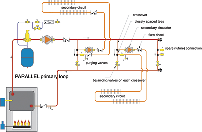
The balancing valve in each crossover allows flows to be balanced in proportion to the load served by each secondary circuit.
Given the additional fittings and balancing valves that are needed, parallel primary loops are more expensive and time consuming to build than are series primary loops. Given the advantages they offer, the market has developed new products for designers to gain the advantages of parallel primary loops using few site-built components.
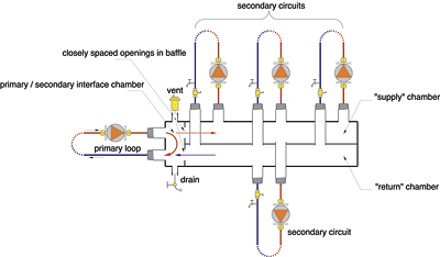
A cross-sectional drawing of this device is shown in Figure 2. A small "primary chamber" is located on the left side of this manifold. This chamber has a common wall with the internal header chambers on the right side. Two closely spaced openings through this wall in effect represent two closely spaced tees.
Because the openings are so close together, the pressure drop between them is essentially zero. Thus, the pressure differential across the header chambers on the right side (from supply to return) is also close to zero. The pressure increase created by each secondary circulator is almost entirely "spent" by the time the flow makes it back to the return manifold. This prevents interference between the primary circulator and whichever secondary circulators are operating. The relatively large cross section of the internal manifold chambers makes the pressure differential between adjacent circuits essentially zero.
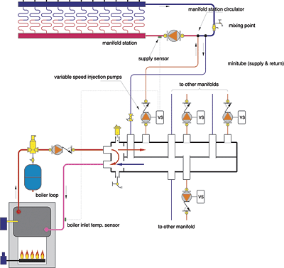
One example of how such a product can be used is shown in Figure 3. This application is a multizone "minitube" system that can supply up to four independently controlled radiant floor heating manifold stations using individual variable-speed injection pumps connected to the P/S manifold. Because each variable-speed injection pump is independently controlled, the supply temperature at each manifold station can be different if necessary. This accommodates situations where different portions of the building have different floor coverings or other characteristics that mandate different supply temperatures to the floor heating circuits.
This approach takes advantage of the relatively large temperature differential available between a conventional boiler and a low temperature floor heating system, especially in industrial buildings, which often have base slab floors. For example, the water temperature in the outgoing minitube piping at design load is typically in the range of 180° to 200°F, while the return minitube is often carrying water at 85° to 95°. The temperature difference between the supply and return minitube is thus in the range of 80° to 100°. In the latter case, each gallon per minute of flow through the minitubes is carrying about 49,000 Btuh along for the ride. In many cases, the minitube sizes can range from 1/2-in. to 1-in., even when high rates of heat transfer are required at the manifold. The small tubing sizes can significantly reduce installation cost relative to systems that perform the mixing operation in the mechanical room rather than at the manifold locations.
Beyond Two Tees
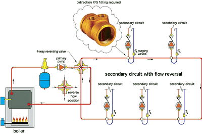
A recently released bi-directional tee can help implement P/S piping.This specialized fitting has a vertical baffle to split the flow path between the left and right secondary circuit ports. This prevents recirculation across the secondary circuit ports. Because the two ports are side by side rather than one in front of the other, they are at exactly the same dynamic pressure. No pressure differential is created to induce flow in the secondary circuit until the secondary circulator turns on.
Unlike a pair of closely spaced tees, this fitting is also bidirectional. Primary circuit flow can be from either direction without physically changing the flow direction through the secondary circuit. Such characteristics allow the possibility of primary loop flow reversal as a means of dealing with higher temperature drops in P/S systems having several secondary circuits connected in series as illustrated in Figure 4.
The four-way valve, in this schematic, acts like a refrigerant reversing valve in a heat pump. Rather than acting as a mixing valve, it simply rotates from one end of its shaft travel to the other on a periodic basis.
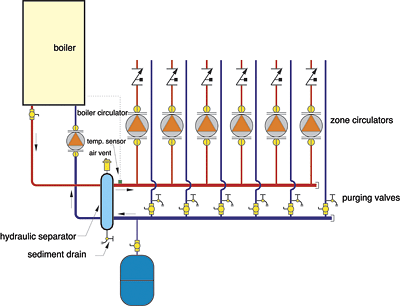
Still another variation on the hydraulic separation concept of P/S piping is possible. This piping system uses a device often referred to as a "low loss header" or "hydraulic separator" between a boiler (primary) loop and a distribution system consisting of several independently controlled zone circulators.
The hydraulic separating device has closely spaced connections on both the primary and secondary circuit connections as well as an area of relatively low flow velocity. These closely spaced connections allow it to isolate the pressure dynamics of the zone circulators from that of the boiler circulator.
The low flow velocity chamber also lets the device function as both an air separating chamber and a sediment accumulator. Notice that the supply temperature to the distribution system is sensed at the outlet of the hydraulic separator rather than at the outlet of the boiler. This arrangement properly senses the net effect of boiler flow mixing with return flow from the distribution system as the zone circulator turns on and off.
A low loss header can also be used to separate the pressure dynamics of a system of multiple boilers from the distribution system they serve as shown in Figure 5.
A low loss header can also be used to isolate various secondary distribution systems from a two-pipe main system as shown in Figure 6. Flow through the primary side of each low loss header remains constant based on the balancing valve setting. Flow on the secondary side can vary as different distribution circuits are turned on and off, or as the three-way mixing valves modulate. This arrangement ensures adequate flow through "flow sensitive," low-mass boilers regardless of the flow situation in the various subsystems.
