The Concept
A dedicated outdoor air system (DOAS) is used to place the required and conditioned ventilation air directly into the space without first mixing it with stale building air, as is the current practice with all-air systems, thus always meeting the requirements of ASHRAE Standard 62 "Ventilation for Acceptable Indoor Air Quality."1This cannot be achieved with confidence in multispace all-air systems as documented in theEngineered Systemsarticle "Fresh Thinking: Dedicated Outdoor Air Systems."2Energy recovery is utilized by the 100% outdoor air (OA) system, as required by ASHRAE Standard 903, thus reducing the size of the chiller and the energy utilized to condition the OA portion of the building load by 75% to 80% over conventional systems.The preconditioned OA is then mechanically cooled so that it can be used to remove all of the space-generated latent (moisture) loads, thus decoupling the space sensible (temperature) and latent loads. Once these loads are decoupled, the remaining space sensible loads can be accommodated with any one of many parallel sensible cooling technologies.
In this "proof-of-concept" project, a chilled ceiling or ceiling radiant panel cooling (here after referred to as radiant cooling) is used to remove the remaining sensible cooling loads. By decoupling the sensible and latent loads, building moisture problems, and the associated IAQ problems, are minimized or eliminated.
Radiant cooling offers further energy savings. First, the pump operating costs to remove the space sensible load are far less than the fan operating costs to remove the same sensible load with an all-air system. And second, with ceiling radiant cooling, the energy balance on the occupants is much different, so the space temperature can be elevated to 78 degrees F with a perception of thermal comfort equivalent to 75 degrees F . This reduces the OA sensible load further as well as reducing the envelope load.
Finally, since the airflow rate with the DOAS is typically only 20% that of a conventional all-air system, high-aspiration diffusers (causing a large secondary flow of room air) are used to ensure that the room does not feel stagnant to the occupants. The high-aspiration diffusers also increase the radiant panel heat removal performance by about 15%. For an overview of the concept, please refer to the ASHRAE Journal article "Dedicated Outdoor Air Systems."4
"Proof-of-Concept" Location
A 3,200-sq-ft architecture studio, used by students in their senior year of school, on the University Park campus was selected as the test site. It houses 40 students and their computers around the clock, seven days per week. The space is currently not cooled. It has one single-glazed exterior exposure, and three interior partitions adjacent to unconditioned spaces. The floor and ceiling are also adjacent to unconditioned spaces. The ceiling height is 14 ft, with pendent illumination at the 9-ft plane.Assessment of the DOAS/radiant-cooling systems potential to garner points based upon the LEED green building rating standard.5 The proof-of-concept DOAS/radiant mechanical system has the potential to generate rating points in five of the major categories: water efficiency, energy and atmosphere, materials and resources, indoor environmental quality, and LEED innovation credits. The DOAS/radiant approach has the potential to generate up to 23 green building rating points, or up to 88% of the minimum points needed for certification.
First and operating cost implications. This approach has the potential to reduce the first cost of the building by $2/ft2 over buildings using conventional, all-air variable-air volume (vav) systems. It also has the potential to reduce the mechanical system operating costs when compared to an all-air vav system by at least $0.10/ft2/yr (or 29% less than a conventional all-air vav system). Because of the demand savings, it also impacts the overall system operating costs, resulting in at least $0.15/ft2/yr.
Health and productivity cost implications. Researchers at the Lawrence Berkeley National Laboratory6 estimate that U.S. companies could save as much as $58 billion annually by preventing sick-building illnesses and could benefit up to $200 billion in productivity increases each year. The proposed DOAS/radiant system will deliver superior IAQ and thermal comfort, thus reducing or eliminating sick building illnesses and related workplace productivity loss.
While specific causes of sick-building illnesses remain elusive, the following have been cited as contributing factors to sick building syndrome7: chemical contaminants from outdoor and indoor sources; biological contaminants that can breed in stagnant water that has accumulated in humidifiers, drain pans, and ducts, or where water has collected on ceiling tiles, insulation, or carpet; and inadequate ventilation.
The DOAS approach effectively eliminates biological contaminants and inadequate ventilation. It also avoids building-wide distribution of indoor chemical contaminants. Therefore, sick building illnesses are significantly or completely eliminated by this approach.
Some Industry Feedback on this Concept
To better understand the need for this proof-of-concept project, the industry's perception of the concept needs to be placed in perspective. Currently the perception is skeptical at best. Specific issues, concerns, and needs are identified below.Concern: Engineers almost universally fear massive radiant panel condensation problems, and want nothing to do with it. For example: Dan IntHout, a Carrier Corporation engineer and product manager, warned that serious water damage from condensation was not an "if" but a "when" issue. Further, he stated that one of their radiant cooling jobs in Europe "caused considerable water damage when condensation fell from overhead cooling panels onto personal computers and sensitive electronic equipment located below." As a result, it was his opinion that Carrier "has serious reservations" about radiant cooling.
Answer: If condensation were the result of the occupancy doubling in a space, the water thickness on the radiant panel after one hour is about 0.0005 of an in. (13µm). For reference, a human hair ranges in diameter from 0.0007 to 0.007 in. (17µm to 181 µm) in diameter.
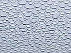
At this rate, it would take one person's latent generation from 90 min to 14 hours for the condensation thickness to equal the diameter of a human hair. Engineers seem to visualize the extreme condensation condition given in Figure 1. This picture is the result of 8.5 hrs of condensation accumulation with the surface temperature intentionally suppressed 14 degrees below the space dewpoint temperature. It is an extreme condition, but even then the beads of water did not grow large enough to form a droplet that fell.
The conclusion, condensation formation is a slow phenomenon, and can easily be responded to by the controls. It is also easy to prevent damaging condensation formation by use of fail-safe controls. Carrier's experience, as communicated by Dan IntHout, is clearly an avoidable occurrence and an anomaly since literally thousands of radiant cooling systems are in operation throughout Europe with no condensation problems.
A professional engineer at a large, Southern U.S. consulting engineering firm raised the following thoughts:
Issue: My designs almost always come out in the area of 250 to 300 sq ft/ton; certainly radiant cooling panels do not have the capacity to accommodate that load.
Answer: Your capacity concern probably comes from an area-based load paradigm. In fact, a large percentage of the design chiller load is a result of the OA load and the space latent loads. When that cooling duty is taken out of the picture, and credit is given for the sensible cooling done by the cold ventilation air, only a portion of the space sensible loads fall onto the panels. In conclusion, panel cooling can meet its capacity duty, and only use about 50% of the ceiling area in most cases. Issue: On chiller size reduction, outdoor air is the driver in our cooling loads, and I have seen OA amounts in the area of 40% to 50% of supply air quantities (outpatient surgery center and courthouse building) after adjusting for ASHRAE's Z-factor. In recent office building work, the numbers have been 20% to 25% OA to SA.
Although a DOAS could eliminate the need for the Z-factor adjustment to system OA (in practice almost always a bump beyond ASHRAE 62-99 tabulated rates on a per person or per sq ft basis), elimination of this bump doesn't seem to be enough of a reduction in OA to significantly affect chiller size, pump size, etc. Even though the space sensible loads are treated differently here, the block cooling load of a given building should not change significantly from one system to another.
Answer: You are correct about the small bump with the relatively small reduction in the OA requirement with the DOAS. You are also very correct to state, "Outdoor air is the driver in our cooling loads." However you have overlooked an extremely important factor. The DOAS approach uses an enthalpy wheel as a part of the 100% OA system, something actually now required by ASHRAE Standard 90. It is here that we see the huge chiller reduction! The enthalpy wheel is able to reduce the OA load at design, as seen by the chiller, by as much as 70% to 80%. This is no small bump! In fact the combined result of heat recovery and reduced OA requirement can frequently lead to a 40% reduction in chiller size. The approximately 30% annual mechanical system energy savings with the DOAS/radiant system is not as dramatic.
Question: On integration of the sprinkler system with the chilled water system8: Although I've heard of this being done, this is an idea that is fraught with danger. Which engineer stamps it? Which trade installs it? Which contractor warrants it? I believe that as a practical matter, the consulting engineering community would resist this idea.
Answer: Trade jurisdiction and design responsibility are important issues. Both the thermal and fire suppression piping fall under the administration of the mechanical subcontractor. If they are also design-build, both the design and installation challenges can be more easily addressed. Many will continue to feel it is not worth the effort. And that is OK from an economic point of view since it is not required to make the DOAS/radiant approach lower in first cost.
Need: Finally, show me an example of the high-aspirating diffuser.
Answer: The ones being using in the proof-of-concept project can be found at http://www.fairchildindustries.com/fci/coldframe.htm.
Based upon the answers given above, the engineer from the large Southern consulting engineering firm admitted that the issues he brought up were partly a smoke screen to veil his fear of being the first engineer at that firm to fail with a radiant cooling job.
Issue: A manufacturer challenged the author with these words: "Look mate, don't even think about trying to get others to adopt your DOAS/radiant approach if you can't get your employer to use it in a campus building."
Answer: The author has accepted that challenge. This proof-of-concept project is the first step.
Need: Universally, engineers want to know where in the United States they can see the DOAS/radiant-cooling system in operation.
Answer: All are welcome to visit this proof-of-concept project, either in person on the PSU-UP campus or by visiting the proof-of-concept web page at: http://doas.psu.edu/poc.html where a virtual tour can be taken, and where the system operation can be monitored via the Web-based real-time controls.
The Proof-of-Concept Project Description
A schematic representation of the project is illustrated in Figure 2. The project consists of major components and capacities noted in Table 1.The dedicated OA system, consisting of the fresh air ventilator unit (FAVU), bottom center in Figure 2, and the cooling coil shown in the center of the schematic, provides constant-volume, variable-temperature ventilation air to the conditioned space.
The DOAS cools and dehumidifies the ventilation air efficiently by using the 75%-effective enthalpy wheel. When the conditioned ventilation air passes through the conditioned space, it is capable of removing the entire space latent load, and up to approximately 3 tons of space sensible load.
The ventilation air is introduced into the conditioned space via high-aspiration (HA) diffusers installed at the 9 ft elevation adjacent to the radiant panels. The HA diffusers have a two-way throw, parallel to the long dimension of the radiant panels. The HA diffusers entrain about 20 cfm of space air for each cfm of discharge air, increasing the convective heat transfer on both the bottom and top sides of the free-hanging radiant panels. The increased air movement is also intended to prevent a feeling of deadness in the conditioned space that might result from the low supply airflow rates compared to conventional all-air designs.
Because of the leaky building site for this proof-of-concept project, great care was exercised in balancing the supply and return flows, via the fans in the FAVU, to ensure that the conditioned space was at a neutral pressure relative to its surroundings. If the space is allowed to go negative, unwanted infiltration and latent load occurs. If the space is allowed to go positive, the energy recovery benefits afforded by the enthalpy wheel begin to diminish.
An air cooled chiller, top center of Figure 2, is used to produce the chilled water needed first by the primary DOAS cooling coil loop, and secondarily by the radiant cooling panel loop. Modulating control valve V1 is used in the primary chiller loop to provide the required flow of chilled water to the cooling coil. Spring return-straight through normally closed modulating control valve V2 is used in the secondary radiant panel loop to vary the panel cooling water temperature. V2 is also a part of the condensation fail-safe control to be discussed in the next section. The pumps in both the primary and secondary loops provide a constant-volume flow.
The eight free-hanging radiant panels are plumbed in parallel, shown schematically on the far left of Figure 2, span the complete 40-ft depth of the conditioned space, and are equally spaced over the 80- ft width of the conditioned space. The panels donated to this proof-of-concept project are manufactured using aluminum extruded fins and eight parallel header copper waterways per 2-ft-wide panel. The cooling water to the panels enters on the fenestration end of the panels, and leaves on the end adjacent to the interior partition.
Simplified Control Description
Since this proof-of-concept project is a single-zone cooling- only application, the controls are very simple. Fundamentally, the DOAS system and the parallel radiant cooling system operate in stages. The constant-volume DOAS unit is the first stage used to meet the space DBT setpoint with a variable supply air temperature. As the cooling load increases, and the DOAS supply air temperature drops to 52 degrees (or a programmable low limit), the supply air is sufficiently dry to maintain a space design DPT of 55 degrees. If the space thermostat is still not satisfied when the first stage is at full capacity, the second stage, radiant cooling, is enabled. Note: The radiant panels are not enabled until the space DPT has been brought under control by the low supply air temperature.
The temperature of the panel supply water is modulated to accommodate the balance of the space sensible load. The space DPT is used to establish a low limit for the radiant panel supply water temperature. The low limit is the space DPT plus 1 to 3?. Since the space has exterior movable-sash fenestration, and access doors that open to unconditioned spaces, their positions are monitored. Their position is not used for control, but education. In the event they are open for a short period of time (the time period is a programmable variable), a harsh and penetrating alarm will sound, prompting the occupants to close what they had left open - even under the duress of peer pressure. The schematic diagram illustrates the humidity, temperature, flow, position, and CO2 points used for control and performance monitoring.
Fail-Safe Condensation Control
A prime objective of this proof-of-concept project is to demonstrate that the issue of condensation control can be reliably achieved. As noted above, some believe that damaging condensation is not a question of "if" but "when." The normal operating control overview was discussed above. In a step to guarantee that damaging condensation cannot form, the simple and inexpensive fail-safe approach used in the project will be discussed.As demonstrated in Figure 1, condensation takes a very long time to form on a horizontal surface. And even after 8.5 hrs, the surface intentionally held 14 degrees below the space dewpoint temperature did not release a drop of condensation. Vertical surfaces are quite a different case. Gravity will cause the moisture beads formed on the uninsulated supply water piping to the panel to run downward. A water sensor is placed at the bottom of a vertical section of the supply piping to receive the water droplets.
The microsensor consists of a sealed, normally closed switch and an expandable element. When water reaches the expandable element, it swells, causing the switch to open. By placing the water sensor switch in series with the control signal to the panel temperature control modulating valve, the signal is zeroed. The modulating panel temperature control valve has a spring return, with the port to the primary loop normally closed.
Therefore, when condensed water droplets are detected, the control valve closes immediately. For redundancy and to overcome the possibility that the normally closed valve spring could fail, multiple water sensors could be employed and the panel pump control signal interrupted like the control valve signal. Water damage from condensation need not and will not be tolerated!

Reasons For Building the Proof-of-concept Project
This project is intended to answer the skepticism of the industry documented above. Central among the topics to be addressed are: condensation, capacity, operating energy, and comfort. It will not answer first-cost questions.The following bulleted items constitute what is expected as outcome from the project.
It is anticipated that the proof-of-concept project will lead to its use in the next campus building. And that as it is replicated elsewhere, strategically located, ASHRAE-sponsored professional development seminars will take place all across America. ES
Jeong Jae-Weon, a Ph.D. candidate was helpful with the early stages of the design and analysis. He has also been working on badly needed new analytical/design tools.
David Thompson, an energy management consultant to the PSU-UP Facilities Engineering Institute nurtured the project through the PSU-UP bureaucracy and secured the Web-based control for the system.
Once the concept was well conceived, equipment suppliers were invited to participate. Their acceptance was immediate and impressive. The suppliers and their contributions are summarized as follows in alphabetical order: American Radiant (panel installation); Automated Logic (controls with Web front end); Bowers Program for Interdisciplinary Design (portion of installation expense); Data Industrial (two liquid flowmeters); Farfield Construction (sheet metal supply and installation); Kele (two three-way control valves); Ling Partnership (electrical design); McClure Co. Mechanical Contractors (working drawings and mechanical installation supervision); PSU Office of Physical Plant (10-ton split system air cooled chiller): SEMCO (FV-2000 fresh air ventilator); Taco Pump (two inline pumps); ThermoTech, Inc. (eight high-aspiration diffusers); Twa/Sterling (eight radiant panel units, 2 ft by 40 ft); USA Coil (coil section for DOAS); West Penn Power Sustainable Energy Fund (portion of the installation expense).
Finally, the author wishes to acknowledge the students that were in his classes: Architectural Engineering (AE) 455-Advanced Hvac System Design; AE 554-Thermal System Simulation and Optimization; and AE 555-Building Automation and Control, over the past few years. They solved many tough homework problems/projects related to this concept, and their gifted minds raised many wonderful technical questions challenging the concept.
Conclusions
The out of the box concept/project discussed in this article has not caught on in the hvac industry, in spite of the author's evangelism on the subject within the university for several years and to the national engineering community for the past year. Perhaps this proof-of-concept project will facilitate moving the hvac industry toward DOAS/radiant cooling. As a wise and experienced consulting engineer from Philadelphia shared after learning about the DOAS/radiant approach: "This concept is radical. It solves problems that I have not been able to solve during my 30 years of practice. This idea is where water source heat pumps were 20 years ago." Acknowledgments
Two of the author's graduate students have been an invaluable assistance in the design and development of the proof of concept project. MS candidate Robert Hedman, obtained information internationally about radiant cooling, developed an optimized design for a cooling panel, and created the DOAS website.
