This article provides an overview of the following criteria commonly used in fan selection:
- Airstream characteristics;
- Capacity;
- Pressure;
- Power;
- Efficiency; and
- Fan and system curves.
Inlet Airstream Conditions
Fan manufacturers' published ratings for airflow, pressure, and power are based on standard laboratory conditions using standard cubic per minute (scfm) for airflow and 0.075 lbm/cu ft for standard fan inlet airstream density.As such, the manufacturer's published ratings can be used for fan selection and evaluation when the deviation between standard density (0.075 lbm/cu ft) and the actual site density at the fan inlet is less than 5%.
This normally occurs when all of the following parameters are met at the fan inlet:
- The fan inlet temperature is between (+)40° F and (+)100°;
- The fan inlet static pressure is between (-)20 in. wg and (+)20 in. wg;
- The fan inlet airstream moisture content is less than 0.02 lbm water/lb of dry air; and
- The fan installation is between ±1,000 ft elevation above sea level (asl).
Corrections for inlet airstream density are calculated by multiplying the standard density, airflow, pressure, and power by the density factor. The density factor (Df) is calculated as following:
- Temperature, °F Dft = (530) Π (460 + inlet temperature, °F);
- Pressure, in. wg Dfp = (407 + inlet pressure) Π 407;
- Moisture, lbm water/lbm dry air Dfm = (1 + v) Π (1 + 1.607v), where v = lbm water/lbm dry air; and
- Elevation, ft above sea level Dfe = [1 - (6.73 x 10⁻⁶)(z)]5.258, where Z = elevation, ft.
- Density factor = (Dft) (Dfp) (Dfm) (Dfe).
- Inlet temperature, 180°F Dft = (530) Π (460 + 180) = 0.828;
- Inlet static pressure, (-)12 in. wg Dfp = [407 + (-12)] Π 407 = 0.971;
- Inlet moisture, 0.025 lbm/lb dry air Dfm = (1 + 0.025) Π [1 + (1.607)(0.025)] = 0.985;
- Elevation, 3,000 ft asl Dfe = [1 - (6.73 x 10⁻⁶) (3,000)]5.258 = 0.898; and
- Density factor Df = (0.828)(0.971)(0.985)(0.898) = 0.711.
- Actual density, Da = (0.711) (0.075 lbm/cu ft) = 0.0533 lbm/cu ft.
Example 2. If a fan is selected for 30,000 cfm, 12 in. static pressure (sp), 1,900 rpm, and 95 hp based on the manufacturer's catalog ratings but installed at the above conditions, then the fan operating performance would be:
- The volumetric capacity would be 30,000 cfm;
- The actual static pressure delivery would be 12 in. wg x 0.711 = 8.53 in. wg; and
- The actual fan shaft hp consumption would be 95 hp x 0.711 = 67.5 hp.
Key point. By properly defining the inlet airstream conditions for density, temperature, pressure, moisture, and elevation, corrections between the fan manufacturer's published ratings and actual operating conditions can be made to ensure proper fan selection and performance.
Fan Capacity
Fan capacity can be stated either in terms of volumetric or mass flow rate.
Mass Flow (lbm/min):
- Basis for fan ratings when a minimum mass flow rate must be maintained;
- Normally stated in units of pounds/minute (lbm/min);
- Represents the mass capacity of the fan at a given speed, static pressure, and inlet density;
- Calculated by multiplying the volumetric flow rate by the actual airstream density at the fan inlet; and
- Varies with changes in inlet airstream density.
- 5 cu ft per scoop x 6 scoops x 1,000 rpm = 30,000 cu ft/min.
- 5 cu ft per scoop x 6 scoops x 1,000 rpm x the mass of the substance conveyed.
Assuming the substance is air at standard conditions and standard density of 0.075 lbm/cu ft, the mass delivery is 30,000 cfm x 0.075 lbm/cu ft = 2.250 lbm/min.
Now assume that the substance is air at non-standard conditions and a density of 0.0533 lbm/cu ft. The mass delivery is 30,000 cfm x 0.0533 lbm/cu ft = 1,599 lbm/min.
If the fan system must maintain a minimum mass flow rate of 2,250 lbm/min at 0.0533 inlet density, the minimum volumetric flow rate is 2,250 lbm/min Π 0.0533 lbm/cu ft = 42,214 cfm, and the fan should be selected on the basis of 42,214 cfm at an inlet density of 0.0533 lbm/cu ft.
Key point: At constant speed, a fan will deliver a constant volumetric flow rate and a variable mass flow rate, with the mass flow rate varying directly with the density factor, or the ratio of actual to standard densities. Volumetric flow rate (cfm):
- Normal basis for fan ratings;
- Normally stated in cfm;
- Represents the volumetric capacity of the fan at a given speed and static pressure; and
- Constant with any inlet airstream condition.
Fan Pressures
The most common pressure used in air moving applications is static pressure. However, a basic understanding of all pressures is essential for the proper selection and operation of fans. These are:- Total pressure (TP);
- Velocity pressure (VP);
- Static pressure (SP);
- Fan static pressure, (FSP) and
- Fan total pressure (FTP).
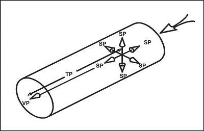
The pressure components of total, static, and velocity pressure are shown in Figure B. Total pressure is parallel to the direction of flow and is measured in the direction of flow. Velocity pressure is parallel to the direction of flow and can only be measured indirectly as the differential between total and static pressures. Static pressure is expressed equally in all directions and is measured perpendicular to the direction of flow.
Total Pressure
Total pressure is the algebraic sum of the velocity pressure and the static pressure at any point in a system and represents the total energy at the point of measurement:- TP = VP + SP.
TP can be either positive or negative, depending on the measurement location.

Velocity Pressure
VP is the kinetic energy in the direction of flow that causes a fluid at rest to flow.- VP = TP - SP;
- VP = (velocity, fpm/1,097)2 x airstream density;
- VP is mutually convertible with SP; and
- VP is always positive, independent of its measurement location.

Static Pressure
SP is the potential energy exerted in all directions by the fluid.- SP = TP - VP; and
- SP is mutually convertible with VP.
SP can be either positive or negative, depending on the measurement location.
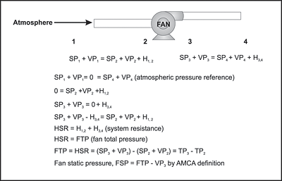
Fan Static Pressure vs. Static Pressure
While SP is the difference in TP and VP, FSP is defined as the FTP minus the fan velocity pressure at the fan outlet, and represents the change in atmospheric pressure by the fan.FSP as defined by AMCA (Air Movement & Control Association) Standards is the basis for fan ratings (Note: In some cases, specialized fans may be rated based on FTP).
Since the FTP equals the difference in the total pressure across the fan, then FSP is expressed as:
- FSP = TPfan - Fan VPoutlet (as defined by AMCA 210);
- FSP = (TPfan outlet - TPfan inlet) - Fan VPoutlet; and
- FSP = (SPoutlet + VPoutlet) - (SPinlet + VPinlet) - VPoutlet.
And since the VPoutlet's are identical and cancel out, then
- FSP = SPoutlet - SPInlet - VPInlet.
However, it is not uncommon to find that the static pressure used for fan selection calculated as: SPoutlet - SPInlet. In this case, the fan is oversized by the VPInlet energy component and can result in excessive energy consumption. The following example shows the excessive (wasted) horsepower from a typical low and high velocity system:
- VPInlet = 0.25 in. wg at 2,000 fpm;
- Cfm = 80,000 efficiency = 75 %;
- Hp = (cfm x VP) Π (6356 x 0.75); and
- Hp = 4.2.
- VPInlet = 1.0 in. wg at 4,000 fpm;
- Cfm = 20,000 efficiency = 75 %;
- Hp = (cfm x VP) Π (6,356 x 0.75); and
- Hp = 4.2.
Using $0.10/kWh, the cost of over design is 4.2 x 0.746 x $0.10 = $0.31/ operating hour.
Calculated on a continuous year basis, this results in an operating cost of 24 hr/day x 7 days/wk x 52 wk/year x $0.31 per hour = $8,736.00.
Additionally, when the static pressure used for fan sizing is calculated in this manner, the fan cannot perform on the fan curve, since the ratings basis between the fan manufacturer and the fan user differs by the velocity pressure component at the fan inlet.
Fan Total Pressure vs. Total Pressure
While TP is the difference in VP and SP, FTP is the increase in total pressure through or across the fan and represents the total work delivered by the fan. FTP as defined by AMCA standards is not normally used for fan rating purposes (Note: In some cases, specialized fans may be rated based on FTP). However, an understanding of FTP is important for a proper understanding and measuring fans and fan systems. FTP is expressed as:- FTP = TPfan outlet - TPfan inlet; and
- FTP = (SPoutlet + VPoutlet) - (SPinlet + VPinlet).
Since the velocity pressures at the fan inlet and the fan outlet are by design normally the same, then the velocity pressures cancel out and the FTP calculation is simplified to:
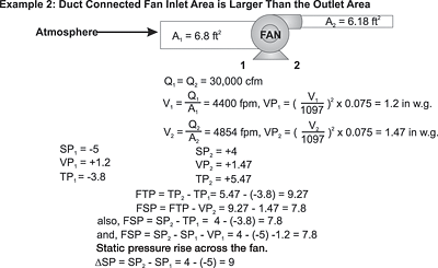
- FTP = (SPoutlet) - (SPinlet)
If the fan inlet and outlet areas are not identical, then this simplification cannot be used.
The above FTP calculation only differs from the FSP calculation by the inlet velocity pressure component.
Since the FTP is simply the sum of the static pressures on the inlet and outlet sides of the fan, when the fan is specified on the basis of summing the inlet and outlet static pressures (static pressure rise across the fan), the fan rating is actually on the total pressure basis.
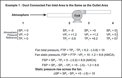
This creates an uneven basis for fan selection and performance, as the fan supplier - unless specifically instructed otherwise - will use this pressure value as fan static pressure, and not fan total pressure. Figures 2, 3, 4, and 5 show fan calculations for various system conditions.
Key point: For optimum energy utilization and fan performance, the static pressure used for fan selection should follow the fan static pressure calculations issued by AMCA Standards for fan performance. ES
