By their very nature, isolation rooms, otherwise known as protective environment rooms, imply a controlled environment. Rooms for patients who need protection against contaminants require positive air pressure relative to the adjoining spaces. No air must be allowed to enter from the outside; the only air permitted is that introduced through the air-handling system. Therefore, the supply, flow, and quality of air must be strictly controlled.
Furthermore, significant air input and movement are required for positive-pressure isolation rooms. The air enters at the ceiling, cascades around, not down over the patient and is then exhausted out near floor level. Consequently, improper sizing or placement of ceiling registers will often cause noticeable drafts.
Patients who are confined to these protective environments are often in residence for a period of months, so the discomfort caused by drafts would have a greater impact than it would on a patient confined to the hospital for a shorter stay. This in turn could have adverse effects on a patient's recovery.
Meeting code requirements
The mechanical/electrical systems for City of Hope not only had to be suited to the unique characteristics of the cancer treatment center, but also had to comply with current California codes for health care facilities, which are more rigorous than the codes of other states and the national guidelines for health care facilities issued by the American Institute of Architects. According to the California code, "The supply outlets and exhaust and return inlets shall be located to provide airflow patterns that prevent stagnation of the air and eliminate short circuiting of the supply to the exhaust or return."Additionally, the codes dictate specific air balance relationships of positive-pressure rooms with adjacent areas as well as the minimum number of air changes per room. The design also had to meet other criteria in conformity with California seismic codes, such as strict requirements for the anchoring of all equipment and the bracing of all ductwork and piping. Compliance is monitored exclusively by the Office of Statewide Health Planning and Development (OSHPD), which also maintains inspectors on site during construction.
Since the ventilation and airflow constraints were identical for so many of the rooms in the cancer treatment center, any error or miscalculation in the design of the mechanical/electrical systems would affect not just a handful of rooms, but virtually the entire facility. Therefore it was essential for the design team at Syska & Hennessey, the firm awarded the mechanical-electrical design contract, to develop a design that could be applied in a fairly uniform way to all the positive-pressure isolation rooms.
Full-scale mock-ups
At the outset, the design team investigated similar rooms in other facilities to study the various combinations of systems used to provide and control airflow. During a nationwide survey of cancer treatment facilities, it was determined that one of the primary causes of patient complaints was the drafts caused by the unsuitable sizing and positioning of the air supply registers in the ceiling above the patients' beds.To experiment with different systems, a full-scale mock-up of an isolation room was built in an outbuilding on the site. While most mock-ups are "passive" and imitate only the "look" of the room, this one included not only all the furniture planned for the room, but also working systems and equipment to simulate the "feel" of the room.
To make the room an "active" one, the appropriate ductwork, ceiling registers, and fans were installed to furnish the volume and flow of air required for the room. Equipment manufacturers willingly "donated" their products to assist in the process. Through the use of working systems, the design team was able to determine the most suitable register location and style for the room under real airflow conditions.
It was felt that resolving the circulation issue for one room would resolve it for the entire facility. In addition, the acoustics resulting from the significant movement of air in the room could be measured as well.
Hospital physicians, nursing staff, and patients, who represented a range of potential users, were invited to get the feel of the room and offer feedback. Many of the suggestions made during this process were incorporated into the final room layout. Medical gas and electrical outlet locations were also identified and confirmed at this stage.
Computer modeling
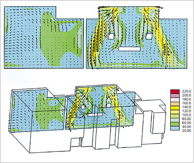
Another innovation was the use of Computational Fluid Dynamics (CFD) to model the air movement in a typical positive-pressure isolation room under varying conditions. The application of CFD in the design of isolation rooms is an unusual undertaking, not typically employed by mechanical design teams. For this phase of the design process, Syska & Hennessey engaged Rowan Williams Davies & Irwin Inc. (RWDI), a firm experienced in modeling air movement in facilities with demanding performance requirements such as performing arts halls, atria, laboratories, animal holding rooms, and museums. RWDI uses CFD to help solve problems involving thermal comfort, air quality, window condensation, and smoke management.For this project, CFD modeling was conducted to study airflow patterns, air temperature, and general thermal comfort conditions within the isolation room and to evaluate the effectiveness of the proposed ventilation system design. The mechanical-electrical design team supplied architectural detail drawings and the required parameters for the room, including supply, return, and exhaust capacities as well as heat load information.
The analysis included simulations with isolation room doors open as well as closed to evaluate whether air from the adjoining space could penetrate into the room, since any air transfer from outside the room could be life threatening to an immunosuppressed patient. In addition, the layout of furniture and equipment in the room, the location of heat-generating devices such as light fixtures, and the temperature gradients around the patient with a physician present were considered.
A significant result of this simulation was the fact that outside air was shown to penetrate through an open door in the CFD model. Therefore, the design team's final conclusion was that the door should be kept closed under normal circumstances.
The CFD modeling provided a great deal of information the designers would not otherwise have had. It was instrumental in determining the location of various devices, most notably the ceiling supply air diffusers, and in resolving the issue of drafts, which has been minimized, if not eliminated completely.

Design parameters
Ultimately, the optimum positioning of individual room supply diffusers and return vents was identified according to the airflow requirements, rather than the architectural design. The designers transferred technology from one medical area to another with the use of radial diffusers, commonly used in medical laboratories, for the ceiling air supply. The air for each 200-sq-ft room is provided by two radial diffusers from Anemostat (Scranton, PA) placed in the ceiling above the patient's bed, one to the left and one to the right.The diffusers, which supply the patient with HEPA-filtered air, have a radial flow pattern that reduces the likelihood of stagnation and are adjustable, permitting changes in the direction of the vertical column of air to prevent drafts. The diffusers also provide a large volume of air relative to their size, an advantage for rooms that require significant air input to meet the OSHPD requirement of 15 air changes per hour (ach). The air is exhausted out through a wall-mounted perforated-plate vent installed about 6 in. above the floor diagonally opposite the patient's bed near the door.
The designers went beyond OSHPD guidelines to allow for an even greater number of air changes: in normal operating mode, the air-handling systems provide 18 ach to the isolation rooms, while in maintenance mode, such as filter replacement, the rate is reduced to approximately 10 ach. This is accomplished by the side-by-side placement and interconnection of the two air-handling systems that provide ventilation to the four floors where the isolation rooms are located. They are designed so that when one system is shut down for maintenance, the other will take up the slack. The design team also introduced an entirely new element into the layout of the isolation units. State and national codes normally require that an anteroom be located outside each positive-pressure isolation room. The anteroom serves as a workstation and functions as an additional air lock to further seal off the room from outside air and prevent contaminants from entering it.
At City of Hope the individual anterooms have been eliminated. Instead, the patient rooms are organized into "pods" of six rooms each, with a 345-sq-ft multipurpose work alcove and nurse and physician work areas that serve as the common air lock for all six rooms. This area is a negative pressure space, evacuating the surplus air extracted from the isolation rooms and exhausting out a greater quantity than it takes in.
Since this new arrangement deviated from the norm, it had to be demonstrated that it would maintain the statutory requirement for positive-negative air balance in order to obtain OSHPD approval. The unconventional design is less costly than the conventional one and has an added virtue - it reduces the "fishbowl effect" that occurs when isolated patients are kept behind the barrier of two doors and draws them into the life of the hospital. This has psychological benefits that can contribute to the healing process.
The bulk of the ventilation system is installed in the ceiling space above the multipurpose area. The area is fitted with a ceiling-mounted modular core diffuser for supply air and a ceiling-mounted exhaust grille. The four cores of the modular diffuser cores can be rotated to control and direct the distribution of air. Circular airflow measuring devices from Air Monitor Corp. (Santa Rosa, CA) were placed in the ducts above the multipurpose area to monitor supply and exhaust air and alert the alarm system if an air balance disruption occurs in a patient's room.
If a problem is detected in air quantity, pressure, or velocity, for example, the devices send a signal to a transmitter control center that activates the alarm panels located outside the room and at the nurses' station. Phoenix Controls Corporation's (Newton, MA) constant-volume control valves are also located in the ductwork above the multipurpose area, where they are easily accessible if adjustments are required. They can be adjusted manually to the desired airflow.
These pressure-independent valves provide an accurate metering of airflow in the patient room by maintaining a constant flow of supply and exhaust air as duct static pressure varies due to the constantly varying system dynamics. Reheat coils are positioned downstream of the supply air valves to heat the air and maintain the desired temperature for each room. Each room is equipped with a limited adjustment wall-mounted thermostat that allows the patient some control for the temperature he or she finds comfortable.
Included in the scope of the project was the provision that mechanical-electrical equipment be able to maintain reliable, continuous operation. To ensure that systems would not be vulnerable to external power disruptions, all electrical units and mechanical equipment were designed so they can operate on emergency power alone, if required.
Diagnosis: success
The use of the room mock-up, combined with CFD modeling, made it possible to pre-engineer the mechanical-electrical systems for the City of Hope cancer treatment facility and provided an effective method of evaluating the performance of crucial systems before the facilities were built. In addition, the information provided by the modeling made it possible to tackle the issues, such as drafts, that have caused patient comfort problems in similar facilities. Allowing the airflow requirements, rather than the architectural design, to determine the placement of supply and exhaust registers eliminated the guesswork often associated with the positioning of mechanical-electrical devices.Although owners are rarely inclined to spend the money to build a working mock-up for mechanical-electrical systems, the investment was worthwhile and the money well spent. Physical testing and CFD modeling have identified and quantified important issues, and provided a framework of clear communication amongst the entire design team. This approach is expected to lead to a successful world-class facility and minimize the potential for costly retrofits.
