
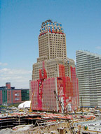
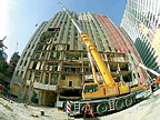
Among the damage from the 9/11 World Trade Center attacks was Verizon's 140 West Street facility in lower Manhattan. Located just across the street from Ground Zero, the original New York Telephone Company headquarters building, constructed in 1926, suffered major damage. Falling steel pierced its walls and façade, tearing open gaping holes. Water from fire hoses and broken water mains flooded its basement vaults, which shorted out cables not already severed by the fallen steel, destroyed the electrical switchgear, ripped loose fuel tanks, and severely compromised the chiller plant. On the exterior, mountains of debris several stories high blocked the ducts, and a thick coating of dust blanketed everything, up to the rooftop cooling towers.
As one of Verizon's largest office buildings in the United States, and its largest switching center in NYC, the 1 million-sq-ft, 32-story structure is a critical telecommunications facility, serving some 300,000 voice lines and 3.5 million data circuits, as well as circuits connected to other telecommunications companies. Within a month, Verizon launched a reconstruction program to both repair the historic structure and improve its systems to better meet present and future needs. Consulting engineers Syska Hennessy Group joined the effort, initially to evaluate the condition of the building, and then to assess the space and develop several options to rehabilitate and/or replace the systems.
The team's objective was to create a state-of-the-art telecommunications center in a landmark building, with a complete infrastructure upgrade that would suit both the telecommunication functions on the lower floors and the administrative functions on the upper ones. Syska Hennessy Group was responsible for the design of mechanical, electrical, plumbing, fire protection, life safety, and central utilities systems.
All the new MEP systems and equipment were designed to furnish the capacity and flexibility necessary for the possible addition of telecommunications equipment in the future. Another key goal was to provide backup for the systems by building in redundancy and to make provisions for essential MEP services to be brought in from outside in the event of emergencies.
The design team also had to contend with a number of other challenges. First, the work had to be carried out expeditiously to complete the rehabilitation as soon as possible. In order to move it along quickly according to construction priorities, the team broke the work down into individual design and construction packages. For example, they issued design documents for the 17th floor, where the new fan farm would be located, as a single package.
Furthermore, the critical nature of the building meant that telecommunication operations could not be interrupted and that existing systems had to keep functioning while the new ones were being built and integrated into the structure. Thus, the new chiller plant on the first floor had to be constructed while the electrical service was maintained just below it, so work could not be performed in that area. In addition, the plant was designed for installation while a satellite chiller plant was kept in operation. Finally, because the building has landmark status, specific guidelines to avoid interfering with its historic features also came into play.
Greater Cooling Requirements
Technological changes that permit a larger number of processes executed by ever-smaller equipment have led to higher electrical loads per square foot and the need for greater cooling in a building of this type. Therefore, an entirely new central refrigeration plant was built to produce all the chilled water required for cooling the facility.Redundancy was built into the plant by utilizing four 800-ton-capacity electric centrifugal chillers with associated chilled and condenser water pumps for an N + 1 capacity. The design also allows for the future connection up to 1,600 tons of additional capacity should the cooling load grow in the future. The plant includes two plate-and-frame-type heat exchangers to provide free cooling when outdoor conditions permit. To prevent damage or outage in case of flooding, the plant was located on the first floor, rather than in the basement where the previous one had been.
Each of the telecommunications floors from three to ten received two mechanical equipment rooms (MERs), at diagonally opposite corners, to reduce the risk of losing both in the event of an emergency. Each of the MERs includes two AHUs, either one of which is capable of handling the entire design load. In this state-of-the-art cooling system, the air is distributed beneath raised floors, leaving the maximum space free to house switching equipment. To protect the telecommunications equipment, water risers run through the MERs rather than through the telecomm space.
A Centralized Approach
For construction cost savings, energy efficiency, and ease of maintenance, the new design incorporates a centralized fan farm of mechanical equipment to serve the administration floors from 11 through 32, replacing 18 independent MERs scattered throughout the building. It includes six new 63,000-cfm AHUs, three on the north side of the floor and three on the south. The engineers took advantage of the double-height clear space of the 17th floor to create the new mechanical space. Elsewhere in the building, all existing fans were refurbished, and, to further improve energy efficiency, fans and pumps received VSDs and high-efficiency motors.New Con Edison 460V electric service and distribution replaced the former 208V service. Network protector vaults moved from below grade to the second floor, again to avoid damage in case of flooding. Since it is essential for the facility to function around the clock, provisions also allowed for emergency electricity generation. On the tenth floor, four new 2 MW diesel generators, two on the east side and two on the west, provide on-site backup for electrical systems to ensure that service will not be interrupted in the event of a power failure.
A new fuel oil distribution system, which includes pumps, piping, two 20,000-gallon tanks and one 17,000-gallon tank, and a control system, now feeds the generators. The fuel tanks sit on opposite sides of the building's lowest level. Each is designed to serve the generators on its own side, but fuel can also be pumped from one tank to another if necessary. The tanks are secured to remain in place in case of flooding or other problems in the vaults.
A series of upgrades on the Con Edison steam service brought the system up to the latest code requirements. The vacuum condensate return pump for the perimeter steam system relocated to above the lowest level to avoid flood conditions. The perimeter steam system was repaired, and pressure reducing valve stations for both the perimeter AHUs were upgraded and one new unit was added.
Enhanced Plumbing And Early Fire Detection
New bathroom facilities replaced the aging and outmoded plumbing systems, joined by new sanitary waste and ventilation piping, and new domestic hot and cold water supply systems including a central chiller drinking water system. The original house tanks for incoming water were refurbished, and new domestic water house pumps of a sealed waterproof type at the fourth basement level can now operate during basement flooding.Local booster pumps at the roof level increase the water pressure on the floors nearest the roof. All new domestic water and sanitary services tie in to the external water and sewer mains operated by the Department of Environmental Protection. New piping, roof leaders, and drains for storm drainage were added as well.
Risers were replaced or installed throughout the building, including new toilet exhaust risers. Unlike the earlier masonry shafts that ran all the way up the building from basement to roof, these shortened risers serve smaller zones. Installing the new risers from the basement to the tenth floor required special care to avoid disturbing telecommunications operations.
The building was already equipped with an early warning fire detection system of fairly recent vintage. After identifying the elements that were still operable, the engineers were able to work with the vendor on necessary upgrades. New standpipes were added as dictated by the floor layout and code requirements for maximum hose lengths. Engineers rehabilitated and expanded the sprinkler system to cover the administrative floors, where there had previously been no sprinklers.
The BMS was upgraded to a centralized, DDC system with a high-speed Ethernet backbone. The system architecture supports equipment integration to major HVAC and electrical manufacturers. The BMS is a peer-to-peer, networked, standalone, distributed control system. System features included Web-accessible control system capabilities; allowing building information to be viewed via standard Web browsers utilizing SSL (secure socket layers) encryption technology. The new system is designed to ensure the optimal operation of all MEP equipment and systems.
Complicating Factors
The physical characteristics of the building and the landmark constraints added to the complexity of the project. Landmark guidelines prohibited creating new openings where they might be needed to admit fresh air. Although the louver space was adequate in some areas, in others it was not.On the 17th floor, for example, there was sufficient window space to build louvers for the fan farm, but in other cases, alternative solutions had to be found. On the tenth floor, the backup generators were placed below a roof setback, since there were not enough windows for the amount of supply and exhaust air required. New remote radiators reduced cooling air required in the generator space. Instead of being concentrated in one area, the exhaust air was spread out across the building's façade by utilizing multiple exhaust fans at each window. In the lobby, which also has landmark designation, the engineers were obliged to incorporate the new HVAC and smoke purge systems within openings already present, including those found in the original plasterwork and ornamental features.
By the fall of 2003, the new systems were undergoing testing, balancing, and startup. The new telecommunications equipment was up and running, and personnel were beginning to occupy the administrative floors. The successful completion of the project demonstrates the ability to design advanced technical systems that can be built quickly and efficiently, with both cost and operational savings. The result is a facility that is more functional and reliable, with greater infrastructure capacity to serve users now and in the future, and is at the same time more energy efficient and environmentally friendly. ES
