Compressor Hall houses the refrigeration plant for a major manufacturer in Missouri, and the people running its new ammonia refrigeration system handle stockhouse cooling and dehumidification, product cooling, water chilling, secondary refrigerant cooling, and space air conditioning for their employer’s largest and oldest facility. The company is Anheuser-Busch (St. Louis), and their product is beer.

Old System: Barley Adequate
The old ammonia plant serving the 100-acre site included equipment ranging from 72 years old to 25 years new. The old plant was becoming increasingly unreliable in supporting the highly automated brewing and packaging production facilities. Multiple expansions had left equipment installed in five separate buildings. High operating costs and environmental issues finally paved the way for the renovation, which began in 1992.The original system was comprised of horizontal, double-acting, low-speed reciprocating compressors; wooden cooling towers; horizontal and vertical water-cooled condensers; and other auxiliary equipment. Synchronous dc motors powered the compressors.
The plant's capacity was around 10,500 tons of refrigertion (TR) (37 mW), powered by 18,000 hp (31.4 mW). The system operated on dual-suction pressures, with a common discharge pressure. The low-suction pressure was 22 psig, 8?F (1.5 bar, -13.3?C). In essence, the capacity of the old plant reflected the old operating conditions.
Moreover, the vibration, noise, and leaks made the plant feel and smell like an ammonia plant. The only thing keeping ammonia exposure limits within regulation was an elaborate exhaust system around the packing glands that directed releases to a large ammonia scrubber. Several truck loads of ammonia were purchased periodically to make up for routine ammonia losses.
Decommissioning the old ammonia plant had its challenges, including:
- Severing all connections between the operating ammonia plant and old plant;
- Removing ammonia from equipment and piping;
- Ensuring that no detectable traces of ammonia residues remained in pipes, or equipment;
- Carefully demolishing the old equipment; and
- Carefully removing and disposing of tremendous quantities of wooden struc- tures saturated with chemicals from the old cooling towers.
Operations were switched over to the new plant while the old one was still up, however, to provide continuous service.

New System: A Case Of Quality
The new refrigeration plant was commissioned and placed in full service in 1996.Consolidated into the two-story, 44,000-sq-ft Compressor Hall, the system has a nominal capacity of 17,000 TR (59.8 MW). The plant equipment is driven by nearly 20,000 hp (14.5 MW) of electric motors. Flooded ammonia is used in all evaporators.
What follows is a more detailed tour of the new equipment.

Trapped, Compressed, And Condensed
There are three 12-ft suction traps. Two operate on low-suction pressure and one operates on high-suction pressure, but they can be cross-connected and operated at a single-suction pressure.The suction pipes connecting the evaporators to the suction traps are also fitted with drain pots to act as primary liquid traps. Ammonia suction pipe headers entering and exiting the suction traps are arranged to effectively remove entrained liquid. The inlet pipes are turned 90 degrees downward, and the outlet pipes are turned 90 degrees upward inside the suction traps. This arrangement ensures that any wet vapor changes direction twice inside the traps before the vapor enters the compressors. The trap design also ensures safe separation velocity and liquid heights.
The 12 ammonia twin-screw compressors operate on 30 psig, 16.5?F (2.07 bar, -8.6?C) and 45 psig, 30?F (3.1 bar, -1.1?C) suction. Each compressor is rated at 1,315 TR to 1,620 TR (4.6 MW to 5.7 mW), depending on the operating suction and discharge pressures. Each compressor is powered by a 1,500-hp (1,119 kW) electric motor.
Compressor oil is cooled using ammonia as a coolant employing the thermo-syphon principle. Liquid ammonia flows inside the tubes, and the oil flows in the shell of shell-and-tube heat exchangers. Liquid ammonia flow varies based on heat load. Oil flow is regulated by a three-way thermostatic mixing valve to maintain the desired oil temperature. Liquid ammonia is supplied to the oil coolers from the high-pressure liquid receivers, which are located on the second floor above the oil coolers. A liquid distribution header supplies the liquid ammonia to all oil coolers from the lower portions of the liquid receivers. Similarly, a central distribution header returns ammonia from the oil coolers to the top of the high-pressure receivers.
Cycling oil pumps are used on all compressors to conserve energy. Four compressors are equipped with full-time cycling oil pumps to allow for a "black" plant start up.
Compressor lubrication oil is pumped from a bulk-oil storage tank to charge each compressor through a hard-piped, oil-charging header. Oil is later removed from the ammonia compressors into two central oil receiver/distiller tanks through a hard-piped oil-removal header. This design eliminates oil handling at each compressor.
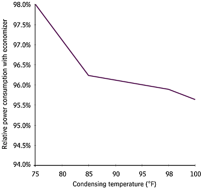
The compressors are equipped with side port economizers that increase the efficiency of the plant by 3% to 4% (Figure 1).
All compressors discharge hot gas into common hot gas headers connecting the compressors to the condensers and receivers. Two discharge isolation valves are installed on each compressor to ensure high confidence of isolating a compressor from the common hot gas headers. A check valve is installed on each compressor's hot gas header to prevent back flow.
Because most of the ammonia hot gas headers are installed outdoors, liquid condenses inside these headers during cold temperatures and reduced flow. The hot gas headers are sloped and fitted with low-point drain pots to drain and collect the condensed liquid. Level switches installed on the pots warn operators of liquid ammonia accumulation in the pots and energize electric heaters installed around the pots to boil off any liquid ammonia.
Six 24-in. suction headers connect the compressor suctions to the three suction traps. Branch pipes to the compressors are connected to the top of the main header. The main headers are equipped with low-point drain pots to assure that only dry gas is supplied to the compressors.
The 12 induced-draft evaporative condensers are each fitted with two 40-hp fans and two 7.5-hp circulating water pumps. The condensers are spaced on the building roof to reduce short cycling. Each condenser is equipped with two sump-mounted water-circulating pumps. All condensers are connected to common ammonia hot gas, ammonia liquid drain, ammonia purge, water-distribution, and water-drain headers.
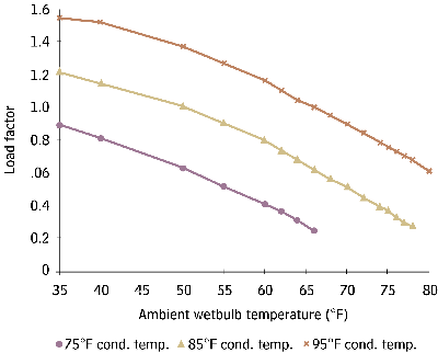
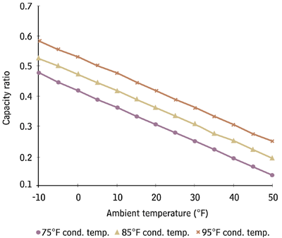
The evaporative condensers are designed to control the ammonia condensing temperature to 95?F (35?C) with an ambient wetbulb temperature of 78?F (25.6?C). A balance was designed to either select more compressors and fewer condensers operating at high head pressure, or fewer compressors operating and more condensers at low head pressure (see Figures 2, 3, and 4).

Thermo-syphoned And Subcooled
Six vertical, high-pressure liquid ammonia receivers are installed on the second floor below the evaporative condensers and above the ammonia compressors. They function as combined thermo-syphon drop receivers and liquid storage receivers. Liquid ammonia is drained by gravity from the condensers into the receivers. The bottom volume of the receivers is piped to ensure a constant supply of liquid ammonia to compressor oil coolers.Return piping from the oil coolers is elevated above the receivers to ensure proper separation of gas from the thermo-syphon return headers into the receivers. The remaining volume of the receivers supplies liquid ammonia to the evaporators.
High-pressure liquid ammonia is subcooled by shell-and-tube heat exchangers prior to distribution to the evaporators. Ammonia supplied from the receivers to the evaporators flows though the tubes and is subcooled by a split stream that flows through the shell side. The evaporated gas from the shell side is fed to the economizer ports on the compressors at an intermediate pressure of 67 psig (4.6 bar).
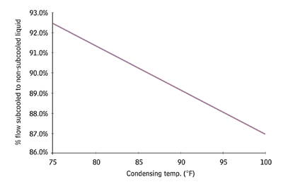
The liquid ammonia is subcooled to prevent flashing in the distribution headers, since many of the evaporators are a great distance from the Compressor Hall and at higher elevations. This ensures that all evaporators are supplied with only liquid ammonia and not gaseous ammonia. In addition, subcooled liquid increases the refrigeration system efficiency. A number of existing evaporators were sized for subcooled liquid flow (Figure 6).
The vapor generated in the ammonia subcooler is supplied to the economizer of the compressors. The suction pressure of the ammonia subcooler is regulated by the economizer port pressure. If the ammonia subcooling load exceeds the flow capacity of the economizers, the excess ammonia vapor is transferred to the suction of the compressors.
The subcooled high-pressure liquid ammonia is distributed to the evaporators in two 8-in. (200 mm) insulated pipe headers. Various head and relief valves prevent unwanted transfer of liquid ammonia to other areas and relieve any hydrostatic pressure.
Headed Off And Boiled
Dozens of suction headers connect the evaporators to three main suction headers: two 30-in. (762 mm) and one 24-in. (610 mm). Each header is piped to a low-point liquid collection pot to trap entrained liquid at the source. The collection pots are fitted with liquid level switches, and electric heaters. When the liquid ammonia level builds up to the marked level, the electric heater is energized to boil off the liquid. If the liquid level builds up to a high-level mark, an alarm is indicated in the central control room signaling unusual liquid carryover. High liquid levels can be pumped out of these traps before the liquid reaches the main suction traps.
The ammonia hot gas headers connect the compressors, condensers, and receivers, equalizing system pressure. System pressure is controlled from a central sensing point on the equalizing headers.
Pumped, Purged, And Scrubbed
Six electric, piston-driven, positive-displacement liquid ammonia pumps are used to transfer liquid ammonia from the low-pressure suction traps to the high-pressure liquid receivers. Two design features are incorporated in the piping design in order to reduce the chance of the pumps becoming vapor-bound. The suction of the pump is vented to the gas side of the suction trap, and a solenoid valve is installed between the suction and discharge of the pump to equalize the pressure across the pump when the pump cycles off.Automatic purgers are installed to remove non-condensable gases from the ammonia condenser coils and receivers. A purge connection is installed on the liquid outlet pipe of each condenser and in the gas space of each receiver. All purge points are piped to a refrigerant-type purger. Purge points are monitored and cycled from the refrigeration control system.
The actual ammonia liquid pressure/temperature are compared to theoretical values to verify the performance of the purgers.
Pump-out compressors are installed to pump ammonia out of the equipment and piping during maintenance. The pump-out compressors are water-cooled reciprocating compressors. The cooling water is drained from the compressor cooling jackets when the compressor stops to prevent freeze damage. Discharge from the compressors can be directed to the ammonia suction headers or to the atmosphere to minimize the amount of ammonia released to the atmosphere and to prevent the discharge of air into the ammonia system.
A single-packed tower water scrubber is connected to the discharge of the pump-out compressors to prevent venting ammonia to the atmosphere. The scrubber is simple and effective in removing ammonia from the gas stream. The ammonia is absorbed into water and discharged to the brewery's wastewater treatment plant.
Two carbon steel vessels with external steam heating coils are used to boil off ammonia from the ammonia-laden oil drained into the distillers from the various evaporators. Ammonia recovered from the oil is vented into the system. The ammonia-free oil is then pumped into tanker trucks for proper disposal.
The amount of oil routinely drained from the refrigeration system has been greatly reduced with the installation of the new screw compressors. This has reduced the manpower cost of draining oil from evaporators, increased the efficiency of the evaporators, reduced the cost of replacement oil, and reduced the cost of oil disposal.
A 1,500-gal (5,678 liter) tank, pump, and distribution pipes are installed to charge oil to each compressor from a central location. This system allows for the bulk delivery of compressor oil and eliminates the manpower cost and hazards of handling 55-gal oil drums.
the supporting cast: water, chemicals, and air
A continuous flow of water is supplied to each evaporative condenser to make up for water lost due to evaporation, and drift. Water overflows continuously to each condenser sump to maintain a consistent water quality in all condenser sumps.
The overflow water then flows through a central tank located on the first floor of the Compressor Hall. From this tank the water is pumped back to the evaporative condenser sumps. At the pump discharge, the water is run though a mechanical strainer and chemical analyzers. Water treatment chemicals are injected as needed to maintain the proper water chemistry to prevent corrosion, scale formation, and microbiological activity in the cooling water.
The local condenser water circulating pumps circulate the water from the condenser sump over the ammonia coils. This ensures proper flow distribution over the entire ammonia coil.
Chemical treatment is supplied to the condensers in proportion to the condenser load. The chemical treatment system provides corrosion protection, controls bacteriological growth, and ensures heat transfer surfaces are clear of scale build up. Blow down is regulated to control the total dissolved solids in the water. Central bulk tanks and pumps are installed to deliver the chemicals into the system.
Ammonia sensors are strategically located throughout the building to sense ammonia. The sensors are connected to the building control and safety systems. The sensors activate the building ventilation system to evacuate the building if ammonia levels exceed 50 ppm. The control panel for the ammonia sensors is located outside the building. In case of ammonia leaks, the operators can determine the location of high ammonia concentrations.
Outside air is used to ventilate the building and to remove the heat generated by equipment. The outside air flow supplied to the building is regulated between minimum and maximum levels. The minimum level ensures that the outside air meets requirements set by ASHRAE 15 guidelines for the ammonia plant. The maximum level is set by the outdoor temperature and refrigeration plant load profile. Power for the ventilation equipment adds up to 320 hp (239 kW). A control scheme is employed to cycle the ventilation equipment based on the outdoor air temperature and projected load profile.
A Smooth Finish
Thanks to the dedication and cooperation of plant operations and corporate engineering staff, the project was a complete success. There was no reportable release of ammonia at any stage of the project, and the improvements virtually eliminated fugitive emissions due to use of welded pipes and valves. The ammonia system is now fully automated but still responsive; its control system ties compressor microprocessors into a custom distributed control system (DCS).The end result is a simple, flexible, and efficient refrigeration plant. Once everything was ready, the staff charged 50 tons of ammonia into the new system and switched over operations for good. ES
