Typical Sites, Common Problems
Many of the sites we have visited consist of centrifugal chillers with a single pump system and a radial distribution piping network. The buildings¿ hvac systems typically consist of built-up air-handling units (AHUs) with preheat, cooling, and reheat coils. In order to comply with FDA guidelines in research, development, and some pharmaceutical processes, space temperature and humidity are closely monitored, controlled, and recorded.With such critical space conditions, it is understandable why a majority of the AHUs were installed both with three-way type cooling coil valves and the old adage, ¿if it isn¿t broken, don¿t fix it.¿ One can see why many central cooling facilities are suffering from inefficient operation and high-energy usage. In dealing with modern district cooling and central chilled-water facilities, many design and plant engineers are faced with some of the following questions or problems.
- Cooling equipment operating with less-than-designed water temperature differentials.
- Building maintenance staff complaints regarding building pumps being too small because of high-return pressures at the central plant.
- Booster pumps being added in series with distribution pumps because of a shortage of cooling capacity in remote areas.
- Cooling water systems designed with a continuous bypass in the distribution system.
- Single variable-speed drives (vsd¿s) were stepped between more than one pump.
- What is the most cost-effective way to reduce or phase out the use of CFC-containing refrigerants? How can multiple buildings with standalone chillers be combined to operate more efficiently?
- Which is better, a radial or looped chilled-water distribution system?
- Can absorption chillers be utilized and still meet building humidification requirements?
- How can the installation cost of a new chilled-water distribution system be reduced?
- Can energy costs be reduced through the use of thermal storage?
- Some facility operators are unaware of where the energy they are producing is being utilized.
The following sections of this article will illustrate and describe how to address a few of these issues during typical site investigations and through detailed designs of district cooling systems in the pharmaceutical industry.
Low Water Pressure
Existing conditions.This central facility was a 10,000-ton centrifugal chiller plant with a radial distribution system to multiple process- and R&D-type endusers. A combination chiller-distribution pump and variable-speed facility pumps handled pumping needs. The complaint was that the buildings were suffering from inadequate chilled-water flow because the return pressures in the central plant were too high and the building pumps could not overcome the plant return water pressure.Site evaluation and correction. Site investigation found that the plant¿s chiller circulating pumps were capable of pumping through the chiller, distribution piping, and many of the closer complexes. It was also discovered that there was no central plant chilled-water bypass. The variable-speed building pumps were piped directly in series with the chiller pumps without being decoupled and were controlled by building differential pressure.
The problem ended up being a simple matter of hydraulics. When the building coils were satisfied for the complexes closest to the central plant, the variable-speed building pumps would reduce speed. However, the chiller pumps would continue to move water through the building loop, further reducing the vsd. Eventually, the building pump speed would slow to a point where chilled water could not be returned to the plant at all.
The correction to the situation was to install a short section of piping to decouple the building operation from the central plant operation. This simple solution allowed the building pumps to perform as designed without adverse effects from the chiller pumps.
Low Water Temperature Differentials
Another particular project started out as an evaluation to determine why an existing 6,800-ton central plant was suffering from low differential water temperatures. It ended up as a multiphase construction project where just about all of the district cooling concepts were applied.Existing conditions. The 6,800-ton central facility was a single-pump system that served the research, development, and pharmaceuticals process facilities through a radial distribution scheme. The system was designed for a 42?F supply water temperature and a return temperature of 56?F, but it was experiencing return water temperatures from the various buildings ranging from 48? to 52?F. The site design-connected load was 4,800 tons with expected growth to reach 8,800 tons over the next five years. Another item that had to be considered in the project was the client¿s philosophy that there had to be sufficient redundant capacity should the largest chiller be out of service (a 2,000-ton unit in this case), the site would still be capable of meeting the cooling demand requirements.
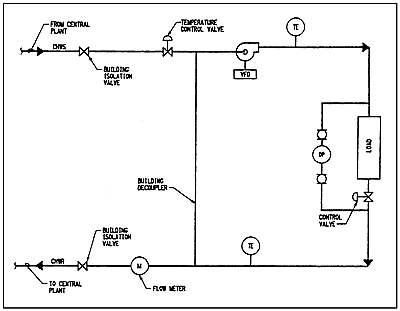
Site evaluation. The existing facilities lacked the required metering to determine the actual site peak. Therefore, the first step in the evaluation was to determine the site¿s simultaneous peak load. Through the use of computer modeling, building manager interviews, and gathering data on equipment, it was determined that of the 4,800-ton design-connected load, only 4,100 tons of it occurred simultaneously and that there was approximately 2,500 tons of it being utilized in three-way type cooling coil temperature control valves (approximately a 5,000-gpm continuous flow rate). It was also determined that these three-way valves resulted in the need to operate excess cooling capacity in order to meet the pumping needs in the perimeter facilities (Figure 2).
The next phase of the evaluation was to evaluate the hydraulics problem. The scheme options evaluated consisted of:
- Maintaining the existing system;
- Converting to a primary/secondary scheme; or
- Converting to a primary/secondary/tertiary scheme.
With the need to ensure continuous building flows so that tight temperature and humidity space conditions could be maintained, a primary/secondary/tertiary scheme was selected. The hydraulics evaluation also included conversion from a constant flow system to a variable-speed, constant return temperature system.

Differential pressure monitoring was also included in the building distribution supply lines to control the speed of the secondary pumps. In addition to the above, the controls for each building space requiring tight humidity control were equipped with a humidistat to reset the return water temperature setpoint. However, due to slow response time, these humidistats were later replaced with a minimum mixed-supply water temperature override.
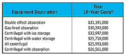
Cooling equipment. Phase III of the project was to determine the method and type of equipment to be utilized in expanding the central plant cooling capacity. By applying the 85% site load factor to the 8,800-ton, projected connected load and a 2,000-ton redundancy, it was determined that the plant cooling capacity had to be increased by approximately 3,000 tons. An in-house economic model was developed to assist in the evaluation of the equipment selection. The model considered the operation of the existing chillers in conjunction with the following optional equipment schemes, operating as either base load or as peaking units:
1) Double-effect absorption.
2) Gas-fired absorption.
3) Motor-driven centrifugals.
4) Options 1, 2, and 3 with ice storage.
5) Options 1, 2, and 3 with cold-water storage.
6) Mixed sized combinations of 1, 2, and 3.

The client opted for the installation of a single 2,000-ton centrifugal chiller to meet their immediate needs and to re-evaluate the situation after a year of operating the upgraded facility.

One Year Wiser
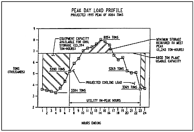
After one year of operation with the new centrifugal chillers, the site was re-evaluated and actual load data was measured. This second evaluation indicated that the site established a new peak demand of 5,730 tons with a design-connected load of 7,750 tons. The site design load was projected to increase to 9,390 tons requiring a plant operating capacity of 8,054 tons or a required increase in cooling capacity of 1,254 tons.
A peak day load profile was developed with the site¿s projected growth incorporated into the profile (Figure 4).


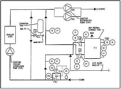
During the first year of construction, as previously described, the plant was designed with a chiller circulating loop as a means of separating chiller operation from distribution demands. It was estimated that it cost approximately $30,000 more a year to pump the total distribution flow the added 60 ft vs. only pumping the tank demand flow 60 ft. The added tank pumps would increase the operator¿s interface with the thermal storage system, but if the tank was piped directly into the bypass leg of the chiller loop, the tank could operate as the bypass. Additionally, the distribution pumps could be used and regeneration of the storage tank would become automatic, depending on the quantity of cooling being provided by the chillers.
Converting to a Central Facility
Many campuses and industrial sites started with individual building chilled-water systems, which more often then not were built with redundant or excess cooling capacity. Now faced with the continued increase in utility costs and a more competitive marketplace, many of these types of facilities are evaluating ways to improve their operating efficiency.Site description. Another one of our recent projects was with a client that had a multiple chiller/building complex with a single-pump, partial-distribution system and wanted to look at centralization. In addition to trying to reduce utility costs, the client was faced with a number of chillers that were over 20 years old and contained CFC-type refrigerants.
Site evaluation. Our first task on a multiple task project was to evaluate the condition of the existing chillers, estimate the actual site¿s present and future cooling needs, and compare it to the installed cooling capacity. This site evaluation indicated that the site had a usable, installed cooling capacity of 3,570 tons with an estimated diversified projected connected load of 6,800 tons. Four of the six chillers evaluated were in need of a major overhaul at an estimated average cost of $40,000 per chiller.
The next task was to develop a phased-type, chilled-water master plan that would allow the client to spread the capital cost over a number of years and still end up with a centralized chilled water facility.
Master plan results. Phase I of the plan was to provide increased cooling capacity and establish a distributive-type, chilled-water pumping scheme. It was decided to remove and replace two of the oldest chillers with two 1,250-ton centrifugal chillers. This brought the total installed cooling capacity up to 5,140 tons.
The most difficult part of Phase I was establishing a pumping scheme that would allow the chillers to be decoupled from the building operation and their associated three-way temperature control valves. A two-pump scheme was selected with chiller circulating pumps and individual building pumps. This allowed the extension of the partial-distribution system on a phased basis and allowed the buildings to become connected as the distribution system was extended.
Another main concern was how to decouple the individual building chillers as they were added to the distribution system. To ensure adequate flows without having a bypass, a single-point decoupler was selected which required each chiller circulating water pump to be sized for parallel pumping and flow control on each chiller. Phase I construction cost was $1,870,000.
Phase II and III extended the distribution system to include the total complex by converting each chiller to a two-pump scheme and adding building pumps to those facilities without pumps. Phase II also had to include the addition of a new facility with excess cooling capacity. The new facility would increase the diversified connected load to 7,200 tons. The estimated construction costs for Phase II and III were $1,600,000 and $1,800,000, respectfully.
The last and final phase was to remove the original remaining four chillers and replace them by constructing a central plant. With 4,000 tons of new chiller capacity being added to the complex, the central plant only needed to be constructed with 3,000 tons of cooling equipment. The estimated cost for constructing the central plant was estimated at $5,100,000.
In summary, a distributive chiller complex can be designed to operate as a central plant with the correctly selected pumping and control scheme.
