
Web hosting facilities (or "Web hotels") can be challenging projects to execute. The power consumption per square foot is very high, necessitating large and complex systems, while the schedules are typically compressed.
This presents unique design considerations for hvac systems. Recently, Parsons successfully constructed an award-winning D-B Web hosting facility in the Atlanta area for a leading telecommunications client. This project was completed and turned over to the client within five months from the start of preliminary design.
This project required 35,000 sq ft of raised floor server space to be constructed in the first phase of construction. The design had to accommodate a final build capability of 110,000 sq ft of raised floor space.
The load density design requirement was 90 W/sq ft. This is a very high load density compared to typical data center or telecom switching facilities. Normally, a load density of 30 to 45 W/sq ft would be the high end of the load range for a telecom or data center facility. The higher watt density is due to the rack-mounted server equipment arrangement in a closely packed configuration with narrow aisles.
The server systems require 24-hr availability, seven days a week. System down time could mean loss of revenues and potentially loss of data for the end customers, and thus was unacceptable. Therefore, an "N+1" redundancy criterion was used for the mechanical systems. For any equipment in the hvac system, there would be one redundant unit available as a standby in the event of a failure.
The only exceptions to this criterion were the underfloor computer room air conditioning units (CRACs). Since the load densities were so high on the server room floor and the server floor area was so large, a failure of a CRAC would be experienced as a local hot spot if only one standby CRAC was provided for the entire raised floor. Therefore, for every six CRACs provided, one redundant spare was provided.
Major Equipment
Due to the fast track nature of the job, and in order to meet the schedule, the client had ordered the long lead equipment prior to Parsons starting design. Parsons tailored the design to the equipment rather than order the equipment based on the project-specific requirements. To cover the first phase of construction, three 600-ton water cooled centrifugal chillers, three 1,800-gpm cross-flow induced draft cooling towers, three 2-MW diesel-fired standby engine-generators, one free cooling heat exchanger, and 29 CRACs were installed. Parsons provided the balance of the equipment required for complete working mechanical systems.Other equipment included AHUs for cooling in the administration, electrical, and mechanical areas, and for ventilation and pressurization in the Web host area; chilled water and condenser water pumps; double-wall, fiberglass underground storage tanks for generator diesel fuel; fuel oil leak detection systems; underfloor leak detection systems; chemical treatment systems; and a bas with remote monitoring capabilities at the network operations center.
Chilled Water System
The chilled water system was designed as a standard primary-secondary system as depicted in the chilled water flow diagram shown in Figure 1.The chillers receive constant flow from the primary pumps regardless of load. The secondary pumps provide variable flow to the load based on a differential pressure transmitter located at the most remote section of the chilled water distribution system. A decoupler loop is provided in the return header to allow the flows for both sets of pumps to balance.
Three 600-ton centrifugal chillers equipped with programmable logic control- based controls were also provided. These chiller control panels had communication capability with the bas. In accordance with ASHRAE 15, relief valves were vented to a safe location outside and emergency ventilation was provided which would be energized from a refrigerant leak detection monitoring system.
Chillers, cooling tower cells, primary chilled water pumps, and condenser water pumps were brought on and offline based on chiller compressor loading as measured by the chiller control panel instrumentation. Field temperature and flow instrumentation was provided so that a load balance could be calculated for the entire system as well as the load going to the raised floor.
This instrumentation was used as a means of measuring the efficiency of the operation of the facility as well as determining remaining capacity for the underfloor cooling system.
Condenser Water System
The condenser water system consisted of cross-flow cooling towers, condenser water pumps, and plate-and-frame heat exchangers used for waterside economizer. The piping arrangement is described in the condenser water flow diagram shown in Figure 2. Each chiller is provided with a dedicated condenser water pump, which is located inside a bypass control valve. This valve is used for changeover to "free cooling," which is defined as the generation of chilled water when the outdoor air temperature is low using only the cooling towers, pumps, and heat exchangers.Upon receiving the start command from the bas, the chiller's primary chilled water pump, condenser water pump, and a cooling tower cell are started. Once flow is established, the chiller compressor starts. The outdoor air wb temperature is calculated by the bas by using temperature and humidity sensors.
The condenser water supply setpoint equals the calculated wb plus the design tower approach of 5 degrees F or 55 degrees , whichever is greater (55 degrees is the minimum condenser water temperature allowable by the chiller manufacturer.) The cooling towers are equipped with vsd fans that modulate to maintain the condenser water supply setpoint.
In order to change over to free cooling, the wb must be below 37 degrees. This 8 degrees equates to sum of the cooling tower and plate-and-frame heat exchanger approach temperatures.
The bas not only looks at wb temperature, but the rate of drop in wb temperature to determine if the changeover will be of a sufficient length to make it economically justifiable to drive down the condenser water temperature. This value of wb change rate is adjustable and can be changed based on historical data for the plant.
The changeover sequence starts by driving down the condenser water temperature. The standby tower is started, as is the free cooling heat exchanger condenser water pump. This is accomplished by disabling the 55 degrees minimum tower temperature restriction in the bas programming.
In order to keep the chillers online during the changeover mode, the bypass valves are modulated to maintain the minimum condenser water temperature to the chillers. Because the condenser water pumps are inside the chiller bypass control valves, mixing of cold water from the towers with recirculated water from the chiller condensers occurs.
Once the condenser water is below 42 degrees, the plate-and-frame heat exchanger chilled water pump is brought on-line and the chillers are shut down. The reverse process is used to switch back from heat exchangers to chillers.
A heat balance is also performed at the cooling towers. Temperature and flow readings are taken for the condenser water supply and return as well as flow readings for the tower makeup and blow down streams. The amount of heat rejected from the tower is calculated by the following formula:
Qtotal = Qsensible + Qlatent
Q = (GPMevap) x 8.34 x 60 x (Treturn - Toawb) + (GPMevap) x 8.34 x 60 x Hfg@oawb
Where:
Treturn = Condenser water return temperature
Toawb = Outside air wb temperature
Hfg@oawb = Latent of vaporization of water at the outside air wb temperature
GPMevap = GPMmakeup - (GPMblowdown + GPMdrift)
and GPMdrift = Total condenser water flow x .00005
This formula accounts for both the latent and sensible cooling of condenser water through the tower. While the sensible cooling portion is insignificant at higher wb temperatures, it accounts for a substantial portion of the total heat rejected at lower temperatures. This calculated heat rejection value is compared to the heat input into the tower that is calculated from condenser water supply and return temperature and flow instrumentation.

AirSide Considerations
The cooling of the Web hosting floor space was accomplished by using underfloor air distribution. The load density of 90 W/sq ft made the arrangement of the servers and CRACs critical to providing proper cooling to all areas.The servers were arranged in large rectangular clusters throughout the space, with CRACs arranged down both sides of the long dimension of these clusters, to ensure that air could be delivered to the spaces properly. Perforated tiles were provided for approximately 18% of the total floor area to allow for enough free area for the required airflow to provide adequate cooling. These tiles were located in the aisles between servers almost continuously.
It appears that 90 W/sq ft is the upper limit of load density where the classic underfloor data center cooling approach can be used. We have successfully used a mixture of overhead and underfloor cooling for high load density areas on other projects, and this would be the approach we would follow for facilities in excess of 90 W/sq ft.
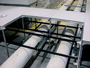
One of the major challenges in being able to install the underfloor cooling system was the allocation of space under the raised floor. The raised floor height used was only 30 in. above finished floor. Much of this underfloor space is occupied by power cabling as well as telecommunications cable tray and wiring.
By necessity, the cable tray was installed tight to the underside of the raised floor system. This was both for accessibility and for providing proper separation between the signal wiring and power cabling. Power cabling, by induction, can interfere with the proper transmission of data in the signal wiring if the two types of cables are located too close to each other. The power cabling was run tight to the floor slab to provide maximum available separation. This left a small lane available in which to run the chilled water piping.
It is imperative to coordinate these lanes when designing a Web hosting project since the available volume is limited. This approach worked very well.
Since the raised floor area was sensitive to water as a potential cause of an outage, drip pans with leak detection tape were installed under all chilled water piping installed under the raised floor. This was done to detect any flange, fitting, or packing leaks prior to experiencing a catastrophic failure of a chilled water branch circuit. If a leak detection alarm was received, the area would be inspected and the leak repaired.
Since the volumes of water being moved under the raised floor are quite large, a line rupture could lead to a significant amount of water flooding the underfloor area. This would almost certainly cause the Web host floor to fail if not addressed.
A small administration area was provided in this facility. This area was cooled with a conventional vav system with fan-powered vav boxes. The supply fan was equipped with a vsd that was controlled by a static pressure transmitter at the far end of the supply ductwork. The return fan was controlled by a fan tracking algorithm to ensure proper ventilation and pressurization rates at varying supply airflows.
The electrical and battery rooms were designed as constant-volume air handlers with vav zones. This worked because the electrical system was designed as two fully redundant parallel busses, an A and B side. The load for the building was extremely flat with no great variations due to environmental or solar loads.
Under normal operation, the load was shared equally at 50% of full bus capacity by busses A and B. During testing or an upset condition, one side could be fully unloaded but charging and the other bus could be carrying 100% of the floor load.
Therefore the overall air handler load did not change, only the distribution of this load. Zone dampers were employed to feed each room. Figure 3 shows the airflow diagram for these systems that fed the battery and uninterruptible power supply rooms. Air handlers are staged in sequence based on a high and low limit for duct static pressure. This approach saved the cost of vav boxes and vsd's.
A battery room ventilation system was provided. This system provided 1 cfm/sq ft of battery room floor. Hydrogen detectors were provided to alarm if the concentration rose above 25% of the lower explosive limit.
Communication is the Key
Due to the compressed schedule, a large field staff was required to quickly process the contractor submittals, resolve field questions, and expedite deliveries. Design was issued in packages to subcontractors in sequence with the construction activities.Design, procurement, and construction were being conducted in parallel. This required good communication between the contractors, the on-site construction support staff, and the client in order to make this project succeed.
Dealing with the technical issues described in this article in a compressed schedule was a challenging experience. However, with the outstanding team assembled to execute this project, it was an enjoyable experience as well. ES
EDITOR'S NOTE: Some images associated with this article do not transfer to the Internet. To review the figures, please refer to the print version of this issue.

