1. Q (flow) a RPM (speed of the fan or pump): in mathematical terms Q1 / Q2 = RPM1 / RPM2;
2. P (pressure) a Q2 (flow): in mathematical terms P1 / P2 = (Q1 / Q2)2; and
3. W (power) a Q3 (flow): in mathematical terms W1 / W2 = (Q1 / Q2)3.
The terms Q(flow) and RPM(speed of the fan or pump) in the above expressions, by virtue of Equation 1, are interchangeable. It is important to note that the above affinity laws as stated are only valid in theory where the flow Q1 has simply been changed to Q2 at the design stage. In this situation, the designer can determine the corresponding revised W2 required delivering the revised flow Q2. The designer can then resize the pump or fan accordingly.
Many engineers recognize the fact that the affinity laws are for theoretical ideal situations; in order to correct for this shortcoming in dealing with a real situation, every engineer brings his own adjustment factor to modify the affinity laws. The above cubic exponent in Equation 3 is modified and substituted by an exponent 2.x, where 0 < x < 9, to be conservative in their energy calculation estimates. There lies the dilemma to the owner, who has commissioned the evaluation of installing a VSD on a pump, for example. There is no consensus on a fixed value of 2.x, as 2.x is characterized by each engineer as "based on experience." This characterization leaves plenty of room for interpretation, as the amount of experience of each engineer is different.
In a hypothetical situation where three different engineers have submitted calculations for the exact same study, and assuming that all three engineers are working on the same exact load profile, all three results will be different because all three engineers would have used three different adjustments of 2.x. None of them could claim with confidence that their results are the correct ones and all of them would be wrong. In this, case what does an owner do since the differences can be quite significant, for example, between 2.1, 2.4, and 2.7 exponents?

Actual Dynamic Conditions
In an actual situation, the design flow and the fan/pump have already been determined, and the goal is to vary the flow Q in proportion to the HVAC loads; this situation is dynamic and it requires at least one controlling parameter such that the fan/pump will deliver the required amount of flow to meet the HVAC end-use demand. There are numerous methods available in defining the control parameters; however, the discussion of the selection of the control parameters is beyond the scope of this article. Suffice it to say that the preferred and most common control parameter has been the pressure in the circuit (air or water).Typically, an HVAC circuit is comprised of multiple branches: the flow to each of the branches is regulated by the opening or closing of a damper (air system) or a two-way valve (water system). As the flow is varied, the total pressure of the circuit varies accordingly as dictated by the affinity laws. The fan or pump can respond more dynamically to a change in pressure in the circuit than to a change in temperature of the returning fluid in the circuit. For this reason, an artificial minimum pressure is maintained in a closed loop circuit.
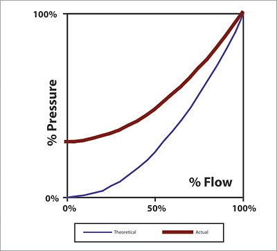
This minimum pressure is expressed as a percentage of the peak design. Per ASHRAE Standard 90.1-2001, this minimum setpoint must not be greater than 1/3 of total design pressure (see §6.3.3.2.2 or §6.3.3.2.3). In an open loop hydraulic system, the pump must overcome a certain amount of lift and thus the typical "square" pressure/flow curve is shifted upward by the amount of required lift. As a consequence, the second law (2) of the above affinity laws is modified in the following manner.
1. P1 / P2 = a + b*(Q1 / Q2)2, where (0< a < 1 and a + b = 1).
In a simplified mathematical term, substituting P1 / P2 = y and Q1 / Q2 = x, the above expression can be modified such that:
2. y = a + b * x2.
This relationship is illustrated in Figure 1 and is comparable to the theoretical ideal relationship between the pressure and flow.
Another expression for the power W is: Wa1 = (Q * P) / (C * h) where C is a unit conversion constant, and h is the efficiency of the fan/pump at the given Q. For two different flow situations, Q1 and Q2, the corresponding power W1 and W2 can be calculated in the following manner in equations (3) and (4) respectively.
3. W1 = (Q1 * P1) / (C * h1);
4. W2 = (Q2 * P2) / (C * h2); and
5. W1 / W2 = [(Q1 * P1) / (C * h1)] / [(Q2 * P2) / (C * h2)].
Eliminating C and rearranging the parameters in the above equation (5) would result in the following equation:
6. W1 / W2 = (Q1 / Q2) * (P1 / P2) * (h2 / h1).
Based on equation (1): P1 / P2 = a + b*(Q1 / Q2)2, the above equation (6) is then reduced to:
7. W1 / W2 = (Q1 / Q2) * (a + b*(Q1 / Q2)2) * (h2 / h1); or
8. W1 / W2 = a*(Q1 / Q2) + b*(Q1 / Q2)3 * (h2 / h1).
Substituting: z = W1 / W2 and x = Q1 / Q2 and assuming (h2 / h1) is ã 1 for the time being, the above equation (8) is simplified as:
9. z = a*x + b*x3, where (0< a £ and a + b = 1).
Equation 9 is only valid for deriving the %W power, input of the fan/pump when compared to the peak design flow, developed by the %Q flow and assuming that the fan/pump efficiency remains constant or near constant over the wide range of flow from 0% to 100% using a VSD. This assumption is true in most cases, because the efficiency curves of a fan/pump are "moved" along the system pressure/flow curve as the speed of the fan/pump is modified accordingly.
In most HVAC situations, a minimum static pressure is used as the controlling parameter in a VAV system pressure (hence the term "static pressure reset" in a VAV system control) or in a variable water volume (VWV) system, except for VSD use in a cooling tower fan. The speed of the cooling tower fan can be regulated by the desired cold water temperature coming out of the cooling tower. In this particular case, a = 0, b = 1, and therefore z = x3 in the above equation (9).
In addition to the minimum required pressure, the VSD-equipped pump/fan might also have a minimum speed requirement to avoid stalling of the fan/pump at low speed.
Although in the above Equation 9, the expression "a" is an estimate as well during the study phase, it is an entity that can be measured in the field after the VSD has been installed and operated correctly for the particular application. Adjustments can then be made accordingly to revise the estimate made in the study phase. As with the 2.x methodology, there is no mechanism available to make the necessary adjustment except for the use of another "fudge factor."

Efficiencies Count
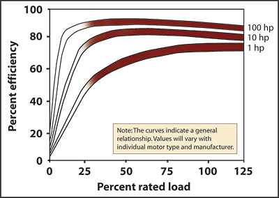
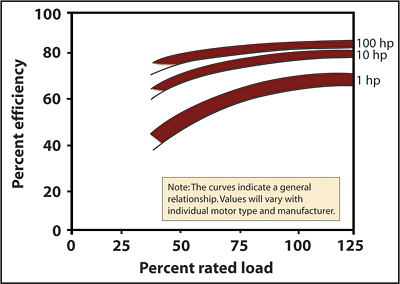
So far the power expression W as stipulated by the affinity laws is defined as the brake horsepower of the fan/pump for any given flow Q. In most real situations, an exact match between the peak design brake horsepower and the selected motor horsepower rating is very unlikely. As a starting point, the fan/pump motor is only partially loaded between 75% and 95%.In 1999, Bernier and Bourret demonstrated the consequences on the energy use of an oversized pump with regard to VSD. With the use of a VSD, the motor loading can be reduced further from a high of between 75% and 95% down to less than 10%. When motors are loaded at less than 25%, the efficiency and power factor of the motor can be severely compromised as illustrated by Figures 2 and 3.
The formulae for the kW electric input to the motor must account for the motor efficiency as well as the drive efficiency at the particular motor and drive loading.
10. kW = BHP(@Q) * 0.746 / (h(motor@Q).* h(drive@Q)),
With h(motor@Q): Motor efficiency at the motor loading developed by the given flow Q; and h(drive@Q): Drive efficiency at the drive loading developed by the given flow Q.
Bernier and Bourret also suggested the following formula for the motor efficiency, and VFD efficiency, respectively:
Where x is the motor/drive loading in percent (whole number).
Another reference for motor efficiency ratings is MotorMaster4+, which contains over 24,000 listings of motors, and has published motor efficiencies for motor loads of 100%, 75%, 50%, and 25%. MotorMaster4+ is a product of the DOE that can be downloaded for free from the Office of Industrial Technology (OIT) website.
Ask the Clearinghouse, publisher of the Energy Matters newsletter, attempted to provide some guidance on the drive efficiencies in the Winter 2002 edition (www.oit.doe.gov/bestpractices/-energymatters/wint-2002_ask.shtml).
The following is an excerpt from this newsletter: "Interpolation can be used for drive/motor loading between two published ranges, and extrapolation can be used for drive/motor loading between 0% and 25% assuming that at near 0% load the drive efficiency approaches 0% as well."
As it is demonstrated in the above Equation 10, the efficiencies terms are in the denominator positions, as motor and drive loadings drop below 25% and approach 0%, the compound effect of the poor motor efficiency and drive efficiency approaches zero. The mathematical value of the kW formulation therefore approaches infinity. Theoretically, it is therefore not recommended to load the combined motor and drive below the 25% limit. This theoretical limitation is in addition to the physical limitation of the motor and drive. Based on the efficiency curve of the 1-hp drive in the above table, it can be concluded that 1-hp motor and fractional horsepower induction motors are not good candidates for VFD applications.
In Equation 8, it is assumed that (h2 / h1) is ã 1. This assumption is true when there is no minimum static pressure in the system curve, because at reduced speed, the fan/pump curve will be shifted along the system curve. In this situation, the fan/pump curve can be characterized as "riding" the system curve. When a minimum pressure exists in the system flow/pressure curve, the fan/pump efficiencies at the various loading conditions must be obtained from the equipment vendor, and the expression (h2 / h1) is ≠ 1. The values of (h2 / h1) must be computed for every loading condition predicted in the evaluation.
The actual situation is more complex than what the affinity laws stated. The most flagrant misuse of the affinity laws is to apply the cubic function directly on the kW formulation by stating that kW1 / kW2 = (Q1 / Q2)3.
The comprehensive formulation for the kW electric power input to the motor is as follows:
It is customary for designers to oversize the fan/pump for a margin of safety, or for the anticipation of future load increase, or for many other reasons. And sometimes "the more the better" mentality is simply applied without any engineering rationale. When this condition exists, the fan/pump is not operated at its best efficiency point (BEP). The same designers then mistakenly think that a VFD will correct for the oversizing situation thanks to the third equation of the affinity laws cited earlier.
Assume that the fans/pumps are typically oversized by 20%. In a closed loop static (i.e., constant volume flow) situation, the affinity laws suggest that using a VFD would correct the brake horsepower on the fans/pumps by (0.83=) 0.51. If the fan/pump motor were oversized by another 20%, the loading on the motor would then be 0.51 * 0.80 = 0.41.
Depending on the motor and VFD size, at 41% loading, the compound efficiency term in the above Equation 11 could be less than acceptable. If the fan/pump is intended for variable flow, the motor is only 41% loaded to begin with, and, in this case, there is a very limited range for this fan/pump to modulate before the motor and drive reaches the 25% loading condition.
When properly sized, the benefits of VSD-controlled fans/pumps are not limited to the fan/pump energy savings in a retrofit situation. There are other side benefits and penalties that are most frequently ignored by the engineer or simply that the engineer is not aware of. When presenting the results to the owner, these side benefits/penalties must be accounted for. The benefits are cooling savings from the reduced fan/pump heat in the air/water stream, and the penalties are increased heating energy use due to the same reductions of fan/pump heat2.
For chilled water system pumping, there are only benefits. For hot water pumping the heating penalties are not negligible, and in some cases the heating penalties can upset the pumping energy savings in terms of fuel and electric costs, making the VSD-controlled hot water pump not economically feasible. As for VAV fan applications, the cooling benefits and heating penalties must be accounted for, taking into consideration the efficiencies of the cooling equipment (COP), the heating equipment (boiler/furnace efficiency) as well as the fuel costs to generate the cooling and heating sources.
It should be noted that the terms VSD and VFD have been used interchangeably in this article. However, VFD is only one of the VSD technologies available. VFD devices are available from numerous manufacturers. Other VSD drive technologies are magnetically coupled. The merits of each of these technologies are not the subject of this paper3. This mention is to make the reader aware of other types of VSD technologies beside the vastly popular VFD.ES
11. kW = BHP(@Q) * 0.746 / (h(motor@Q) * h(drive@Q) * h(a@Q) * h(etc@Q)).
Cited notes
1. This is the generic expression of the shaft power for a fan or a pump. In a pumping application, the specific gravity (s.g.) of the fluid must be accounted for unless the fluid in question is water, then s.g. is 1.
2. For fan applications, the kWh savings can be converted directly to equivalent cooling savings or heating penalties depending on the season if the fan motor is installed within the fan enclosure. For a fan motor mounted outside the fan enclosure like a pump, which is outside of the water stream, the fan/pump brake horsepower figures are used to determine the cooling benefits or heating penalties.
3. Pacific Northwest National Laboratories publication PNNL-13879, Technology Demonstration of Magnetically-Coupled Adjustable Speed Drive Systems, www.eere.energy.gov/-femp/prodtech/pdfs/mag_motors.pdf.
Other References
Ontario Hydro. Adjustable Speed Drive Reference Guide, 4th Edition, Ontario, Canada, 1997.
E Source, Inc. Drivepower, Technology Atlas Series, Volume IV, Boulder, CO, 1999.
U.S. Department of Energy, Office of Industrial Technology, and the Hydraulic Institute. Improving Pumping System Performance, A Source Book for Industry.
U.S. Department of Energy, Energy Environmental and Research Center, and the Air Movement and Control Association International. Improving Fan System Performance, A Source Book for Industry.
Tumin Chan. Engineered Systems, "One Person's Opinion: Affinity Laws," October, 1999.
Pumping System Assessment Tool (PSAT) training workshop by DOE-OIT.
