Why It's Worth the Effort
Integrated building commissioning, where the entire building is treated as a system, is one such process that is gaining wide acceptance as the best way to ensure optimum operation and occupant health and comfort. Within integrated commissioning, moisture control is an often misunderstood, yet critical, area. Uncontrolled moisture in buildings has been estimated to account for up to 80% of premature wear expenditures on built facilities through the flaking of paint, staining of wall surfaces, and rusting of steel. It has also been shown to accelerate the deterioration of furnishings and structural materials, such as wood and wallboard. Furthermore, inadequate moisture control can cause serious problems for occupants and industrial processes (Figure 1).The occupants of a building can be adversely affected by low moisture levels. Similarly, when moisture levels are too high, discomfort and irritation of the mucous membranes, as well as a 'skin-wetness' or sticky feeling can occur.
High moisture content on surfaces can also cause microorganisms to propagate. Microorganisms growing indoors, such as fungi and bacteria, are capable of producing metabolites, protein, and polysaccharide structures that are possibly toxic, inflammatory, or irritating, depending on individual sensitivities and genetic predisposition.
Specific industries also require extremely effective moisture control systems. For example, printing plants require strict humidity control to ensure dimensional stability of the paper and to minimize misalignment in multicolor printing processes. Threads in textile mills may fracture at low humidity levels. Additionally, hospital operating rooms generally have relative humidity (rh) levels controlled at 60% to maintain moisture around exposed tissue and to minimize sparks that might ignite flammable gases, such as oxygen and anesthesia.
Although it is often thought that buildings exposed to prolonged periods of high ambient temperature and high absolute humidity (as is the case in the Southeast, for example) are particularly susceptible, other factors in all parts of the United States can cause moisture-induced problems as well. These are:
- Challenging climates (rainy, hot/humid, extreme cold);
- Complex building envelopes;
- Use of innovative materials (or new applications of existing materials);
- Impacts of hvac systems on building pressurization; and
- Hvac systems serving as a source of moisture.
The American Society of Heating, Refrigerating and Air-Conditioning Engineers, Inc. (ASHRAE) defines commissioning as the "systematic process of ensuring that systems are designed, installed, functionally tested, and capable of being operated and maintained to perform in conformity with design intent."2 Integrated commissioning ensures that the building structure and its component systems are able to work in concert and support the facility's prescribed functional and programmatic needs. It is a quality assurance procedure that starts during planning and design and is carried through construction, occupancy, and operation to ensure the building can meet specific, quantifiable goals.
Controlling Moisture in Occupied Spaces
Buildings must be designed, constructed, and operated to effectively control the impact of moisture. ASHRAE 55-92 has a range of temperature and rh levels to maintain comfort3, and ASHRAE 62-99 specifies that rh levels should be maintained lower than 60%.4The causes of excess moisture in buildings can be broadly classified and traced to either liquid water or water vapor. Although both sources can lead to the same result, the treatment of the two is very different. Liquid water can come from many sources, including rain and snowmelt penetration through the envelope, groundwater entering through the foundation, and leaking pipes and equipment within the structure itself. These items are all serious and can be remedied through application of good building practices.5A more insidious problem, and one that is often difficult to identify early in the operation stage, is the inappropriate condensation of water vapor within the structure. Common sources of water vapor in buildings include vapor pressure-induced diffusion from outside, direct introduction of water vapor from the outside through ventilation system-induced airflow, evaporation from wet surfaces and processes, and mechanical components such as humidifiers.
The envelope, occupied space, and mechanical system must all be designed and constructed to operate together to minimize moisture intrusion into the structure. The building envelope serves as a manmade barrier between the indoors and the outdoors. Maintaining the integrity of the elements of this barrier is essential in controlling moisture. Discontinuities can occur through:
- bridging;
- lation defects;
- Air leakage;
- Penetrations; and
- Component connections.
In commissioning the envelope, a thorough review of the design of the static elements (insulation, vapor retarders, etc.) is essential. An analysis of the envelope system, used to determine the dewpoints that are likely to occur within it, should be made, as should other potential sources of moisture, such as internal activities, humidification, etc. Relevant criteria can be found in the 1997 ASHRAE Handbook of Fundamentals section on "Steady State Design Tools."
Steps to take to control the moisture sources in the hvac system design for dehumidification under full-load operation include:
- Eliminating unvented combustion processes;
- Minimizing vapor pressure differences through use of vapor retarders;
- Minimizing outdoor air infiltration through careful construction and use of pressure relationships; and
- Eliminating cold surfaces within the building envelope.
Since moisture is always present in the air, precautions must be taken to ensure the rh can be maintained below 60%. There are two methods commonly employed: Direct dehumidification with a dehumidifier is often used in small areas, and replacing moisture-laden return air with dry supply air is commonly used in large buildings. In this latter approach, supply air is dehumidified either by passing it through a cooling coil or by passing it over a desiccant material.
When performing a review during commissioning, it is essential that all loads are accounted for and worst case conditions are clearly specified by the designer. Since worst case scenarios generally occur under cool, rainy conditions, the commissioning agent must ensure these conditions are considered during the early design phases.
The interaction between mechanical system operation and the building envelope is critical in controlling moisture. Since even very low infiltration rates can contribute significantly to moisture load, it must be carefully considered and accounted for during design. A key element is the air barrier, and an effective air barrier has the following properties:
- It must be continuous.
- Barrier materials must have a permeability less than 0.004 cfm/ft2 at 0.3-in. wg.
- It must be capable of withstanding both positive and negative pressures.
- Connections must be airtight and flexible. And
- It must be durable.
Ambient air can also penetrate a building through openings in doors and windows.
The control of moisture under partial-load conditions can be particularly problematic. Considerable attention must be paid to ensure that the hvac control logic is reasonable and that the proper sensors are specified and installed in appropriate spaces to support it.
Case Study: Investigation of a Design/Installation Flaw
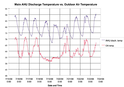
The impact of correcting a design/installation flaw can be extremely beneficial to maximize occupant acceptance and minimize operating cost. An example is a 200,000-sq-ft, four-story medical research building in the Northeast. Originally designed and constructed as an administrative building, it had undergone many renovations and use changes over the last 25 years. Current occupants complained of odor migration, improper temperature control, and ruined experiments, while the owner complained of excessive energy costs and continuous demands on maintenance staff.
The renovations called for 15 air changes per hour (ach) to be delivered to the laboratories, with 50% being outdoor air tempered by chilled water from a central facility. Each laboratory had a separate fancoil unit to help control the heat load from the laboratory equipment, primarily as design days were approached.

What Was Found
Problems were first reported during the construction of an adjoining building. Fearing a reduction in chilled water supply at the research building, the designers installed booster pumps, which through a design installation flaw in the control logic, effectively sent the chilled water back to the chiller plant unused. This resulted in an energy penalty of approximately $100,000/yr. Since the outside air was not being effectively thermally conditioned, the fancoil units were required to operate constantly during the summer months, resulting in higher electrical costs and additional service calls. This also resulted in air with a high moisture content that induced mold to grow in many areas, including on the insulation of the fancoil units in the laboratories (Figure 3).To maintain temperature during the summer, the operating staff reduced the amount of outside air, causing the building to become extremely negative and disrupting pressure relationships as originally established. This resulted in more moisture intrusion and the transfer of odors within the building. Furthermore, the energy management system was disabled and the mechanical system was operated manually.
After careful analysis, it was discovered that the design intent was not being met because of the cumulative impact of several operational problems stemming from a design/installation defect. Renovations were undertaken to correct these problems, generating savings of nearly $80,000/yr in energy usage and $50,000 in service costs.
Equipment and Equipment Rooms
The performance goals of AHUs must be considered carefully since one of their prime functions is to cool and remove moisture from the supply air. This presents two important issues. First, since it is removing moisture from the air, the AHU is itself a source to be controlled. Second, because it generally has significant chilled water piping and other cold surfaces associated with it, these parts become prime areas for condensation to occur.The commissioning agent, through careful design review, must be sure that the cooling coil is appropriately sized to meet the design loads. This will help ensure that the airflow velocity is not high enough to blow condensed droplets from the face of the cooling coil, past the condensate drain pan, and into other areas of the AHU and associated ductwork. This is also termed moisture carryover. The outcome from this could include shortening the equipment life through material degradation caused by internal flooding, compromising insulation effectiveness, or inducing microbial growth.
To prevent the potential for microbial growth, the condensate cannot be allowed to remain in the condensate pan. Simply put, there must be adequate means to collect condensate and the pan must be appropriately sloped to the drain. Although relatively straightforward, this is one area that is often overlooked during installation and start-up periods, often resulting in standing water and/or periodic flooding. The AHU should be installed in accordance with the manufacturer's tolerance for equipment levelness. Additionally, the pan must have an appropriate slope, with the drain at the lowest point. Having the condensate drain pan slope in two planes is ideal, as it helps prevent stagnation within the pan.
Drain lines and traps must also be carefully observed. Drain lines must be appropriately sloped to carry water away from the condensate pan. Furthermore, it is essential they be sized to minimize the potential for blockage by debris that may accumulate through routine equipment operation. It is also important to note that the lines should be checked before start-up to ensure there is no construction debris that could clog the drainage system. All of the drain lines should be connected to a sanitary floor drain.
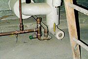
A properly designed condensate trap allows for the discharge of water from the cooling coil drain pan, while the water seal prevents the flow of ambient air into or out of the air handler. Although simple in concept, several problems have been noted in improperly trapped systems, primarily on the suction side of the coil, that lead to moisture problems.
For example, if the trap outlet is too short, negative pressure in the AHU will pull water from the trap into the air handler. When no water remains in the trap, the air seal is lost and air flowing back through the drain line has enough velocity to spray the condensate collecting in the drain pan into the fan intake. Alternatively, if the trap height is too short but the air seal is maintained, the condensate in the drain pan can back up and overflow. Both of these scenarios may result in moisture being distributed into the downstream areas of the unit and possibly into the ducts. This can increase corrosion of the AHU components and detrimentally impact the insulation inside the ductwork as well as promote growth of bacteria and fungi in the system.
Improper trapping can be caused by several factors including poor design, installation, or maintenance of the trap. For example, Figure 4 shows a trap that had a 4 in. height. Unfortunately, the curb should have been cast at the required 6 in. to permit installation of a trap of proper dimensions. Understanding the equipment manufacturer's trapping requirements and allowing for adequate depth will ensure that uncontrolled moisture will not be drawn into the rest of the system.
Moisture must also be controlled in the equipment room itself to prevent corrosion, deterioration of insulation, and colonization by microorganisms. Since the equipment room is often thought of as separate from occupied spaces in the building, precautions are often not taken to minimize moisture intrusion within it. However, due to the nature of the equipment and associated piping that is generally found within these rooms, they must be carefully evaluated during the commissioning process. For example, just as you would evaluate the building envelope during a design review, you would want the mechanical room perimeter walls to be insulated with a low permeability vapor retarder on the warm side. You would also want to ensure that rain water and snow do not penetrate the outdoor air louvers and pool on the floor.
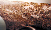
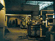
It is often noted that instead of direct ducting for the outside air (the method of choice), the equipment room may be designed to run at negative pressure and air is drawn in through louvers in the exterior wall. This can result in moist outdoor air being drawn in and condensing on cool surfaces. Figure 5 shows a mechanical room that serves as an outside air plenum, while Figure 6 shows uncontrolled condensation and corrosion on the exterior of an AHU due to this type of mechanical room design.
Positively pressurizing the mechanical room can help reduce unplanned moisture condensation. This can be done by dumping the return air into the equipment room or, alternatively, by providing conditioned primary air to pressurize the equipment room.
