Built in 1986, this 745,000-sq-ft facility houses trading operations for 2,400 stock traders, supporting global financial trading, corporate accounting, network services, and telecommunications. Base infrastructure includes 10,000 kVA of UPS power; 14 MW of engine generator; 4,000 tons of chillers; 5,000 tons of cooling towers; and 14.8 kVA of medium-voltage utility power. Over 60,000 sq ft of raised floor data center is required to support processing operations. At the design goal of 50 W/sq ft, over 3 MW of UPS power will be required to support data, telecommunications, and trading floor operations.
Cooling capacity for critical systems and ancillary support areas is more than 2,800 tons. An infrastructure disruption at this facility would interrupt all data processing functions and cause financial losses that could exceed millions of dollars per hour. Even a momentary infrastructure disruption will require hours of computer hardware, software, and database restoration.
Opportunities to schedule any type of downtime were impossible; open-heart surgery would be required to prevent a corporate heart attack.
Glass reached out to Jack Dale Associates, PC (JDA) after attending one of its mission-critical design seminars. The engineering challenge was to develop designs that incorporated phasing plans to avoid any disruption to the critical systems.
’24 By Forever’ Availability
Any critical facility’s ME plant must have fault tolerance, change tolerance, and maintenance tolerance. When these design goals are adhered to, then continuous availability requirements can be supported.Continuous availability provides opportunities for downtime to perform infrastructure maintenance. For the ME system to support the mission of continuous availability it must be fault tolerant, concurrently maintainable, and transparently scaleable.
Fault tolerance is the ability of the infrastructure to sustain an unplanned failure or disruption of any component without impact to the critical loads. Concurrently maintainable designs accommodate the planned removal of any component, at any time, for service. Transparent scalability provides for increasing the cooling capacity without risk to the data process. Long-term strategic modifications were required for the ME systems to adequately serve the critical demands of the data center and trading operations.
Since the penthouse-installed infrastructure for this facility is 150 ft above the ground, accessibility was limited. It was determined that the mechanical systems required N+2 chiller redundancy. This mitigated the loss of large increments of cooling capacity, due to the failure of proprietary parts, equipment age and, in this case, extended downtime required by 14-year-old, 1,000-ton chillers. Redundant piping distribution paths are imperative for concurrent maintenance.
All electric power used to operate computer processing equipment converts to heat and must be cooled. Without cooling, state-of-the-art computer systems will be disrupted or damaged due to overheating, within minutes.
Testing, commissioning, and benchmarking have proven the rate of temperature rise in a modern data center. Without cooling, a 40 W/sq ft data center will rise in temperature faster than 10 degrees F per minute. By the time operators respond to the emergency, the room temperature will exceed 108 degrees, internal server temperatures will rise to 156 degrees, and temperatures inside of server cabinets will exceed 138 degrees.
These alarming statistics demonstrate that a cooling disruption, coupled with the fact that all of the computer systems remain operable on UPS power, will cause thermal damage to sensitive computer systems. While the UPS batteries maintain the operation of the electronic equipment, the lack of cooling would be causing a data processing meltdown.
Data center power density averaged approximately 20 W/sq ft through 2,000 W/sq ft. New generations of technology, including “1-RU servers,” virtual tape systems, “blade technology,” and storage area networks are causing data center power density to rise again.
JDA clients that had 20 W/sq ft data centers ten years ago have seen the power density double to 40 W/sq/ft. Renovations and upgrades to these sites are projecting a need for 60 W/sq ft average power density within the next five years.
JDA testing has demonstrated that at 20 W/sq ft the rate of temperature rise is less than 4 degrees per minute, in the first three minutes. Doubling the power density to 40 W/sq ft causes a rate of temperature rise of slightly more than 10 degrees per minute. Data centers with 60 W/sq ft loads will increase in temperature 15 degrees to 20 degrees per minute! Cooling is essential to protect the critical data processing hardware (Figure 1).
The design standards for data centers have lagged behind the information technology requirements. Table 1 displays how the various information technology functions need to be supported by facility systems. Citigroup began to renovate its data center to align infrastructure support with the IT corporate mission.
IBM statistics compared disruptive events: number of events compared to downtime hours required to restore data center operations. Fifty-five major data center infrastructure failures demonstrated that while 80% of all disruptive events were electrical, more than 75% of the downtime hours were required to restore mechanical disruptions. The conclusion is clear: when a mechanical event occurs, restoration is difficult and time consuming.
The Evolution Of A Crisis
The most common problem in aging facilities is that O&M programs fail to take into account the big picture. These band-aid operations tend to transform simple problems that aren’t working into complex problems that aren’t working.It is usually obvious what the previous designers intended to accomplish but often surprising to find out how the system is actually performing. Often what is left is a tangle of pipe, various sized chillers, various crossover pipes, parallel runs of smaller pipe, and large numbers of seldom-used valves. The first casualty of this type of mess is ease of operation.
At Citigroup, tactical efforts had been implemented to supplement the mechanical plant. The complexity that resulted from these expansions required extensive manual intervention. Mandatory manual interventions are the antithesis of fault tolerance. Reliability and simplicity are interrelated. Glass challenged JDA to simplify the systems, increase capacity and redundancy, while limiting the need for complex automation to control the plant.

A Two-Phase Investigation Of The Data Center
Engineers at JDA set out to perform a thorough mechanical systems diagnostic review of the building’s critical systems infrastructure. Their investigation was enhanced by the use of state-of-the-art electronic equipment, flow testing, and remote universal data recorders to benchmark the operation of selected mechanical subsystems.Operating staff, at first resistant, quickly invested themselves in the process to assist the engineering crews with evaluating the plant. Teaming provided the engineers with information and site inspections that they may have missed, while the operators gained access to engineering theory and calculated performance goals for the existing and new plant.
The benchmarking and testing study of the building’s ME systems occurred in two phases. Phase One benchmarked the existing cooling load requirements and the existing capacity in the central plant, cooling towers (heat rejection), and distribution systems. The aim of this phase was to study the capacity, redundancy, stability, maintainability, and operability of the existing systems. Field testing the condition of the existing infrastructure assisted with understanding the ME system dynamics affecting the site.
System capacities were measured with noninvasive test procedures. Universal data recorders were deployed for a minimum of three weeks to capture system dynamics. System hydraulics discovered through test engineering were compared to as-built drawings and original design documents. The fault tolerance, change tolerance, and maintenance tolerance of the ME systems dedicated to this 24/7 data center operation were developed to establish the design goals.
Conceptualized strategies for increasing central plant capacity and redundancy were produced. Methods were suggested to integrate the proposed solution into the existing ME system with minimum disruption to the operation.
Findings
Results of testing portrayed that the critical server environment wasted computer room air handler (CRAH) capacity and redundancy. Deficiencies included lack of static pressure predictability, poor cabinet/raised floor integration, and flawed chilled water distribution control.At the time of testing, the data center power density was 24.7 W/sq ft. Existing CRAH capacity was insufficient to meet continuous availability goals, and redundant capacity was invaded during hot weather to satisfy the cooling load. Ongoing hardware installations exacerbated the problem by adding additional cooling load on a daily basis.
Makeup water is essential to the operation of a chiller plant. Makeup water volume in this facility’s cooling tower sumps will only last a few hours without makeup supply. At that point, the entire central plant will shut down. A single city water service entered the building, and redundancy was nonexistent. A makeup water storage tank serving double duty as the makeup tank for fire protection water was also used for chiller plant cooling tower makeup. The tank totaled 150,000 gal, with 30,000 gal reserved for fire protection. If the chiller plant requires the use of the makeup reserve tank during hot weather, the 120,000 gal of storage would have lasted 20 to 24 hours at the existing load. When this reserve is exhausted, 8,000-gal storage trucks would, if available, deliver water. At the existing load, an 8,000-gal supply would only have lasted 1 to 2 hours.
Finally, the status and operation of central plant equipment from a single station in the chiller room did not exist. Operators had to physically observe equipment operation and status at each component. To start and stop equipment and verify status, operators crossed the length or width of the room multiple times. In an emergency, the lack of central monitoring wasted time and could lead to a plant disruption.
Projected load growth in the data center could exceed 100 W/sq ft. Electrical wiring design and methods of providing redundancy (dual power cord, static switches, etc.) are well defined.
Flawed Chilled Water Distribution
The distribution of chilled water to both critical and non-critical cooling loads in this building had been problematic since the completion of the construction in 1985. Problems have been reported that range from a lack of chilled water flow to excessive flow that has ruined ATC valves. Evidence of various methods to control this critical problem included the addition of differential pressure controls to a bypass loop in the central plant. These controls were found abandoned in-place.In a further attempt to resolve the flow and pressure control problems, a differential bypass valve station was added on a 6-in. riser loop. The added complexity and poor operation of this valve station led it to be abandoned by operators as well.
Differential pressure was difficult to control. When the differential pressure station opened, chilled water was bypassed back to the central plant. The bypass reduced differential pressure available to the critical loads. It was also possible that some automation valves resisted control air pressure because they were unable to hold against excessive chilled water differential pressure.
Furthermore, segmentation valves in the floor loop piping and central plant were found to be insufficient to provide concurrent maintenance. Repairs of critical valves and pipe would cause the loss of more cooling capacity than the critical load could withstand.
Setting Goals
A problem well defined seeks its own solution. JDA determined that improving the fault tolerance, capacity, and energy efficiency of the ME plant — while preserving capital — would require four strategic efforts:
- First, the facility needed “quick-fixes” to stabilize existing systems. Some of these projects were initiated immediately following the conclusion of testing. Included in this phase was a redesign of existing computer cabinets to integrate them into the raised floor cooling system.
- The second effort needed to address the serious hydraulic problems hindering the chilled water distribution. The effort focused on selected redesign of the existing plant for better control and efficient use of existing capacity.
- Meeting with hardware planning to project power densities that can be accommodated by the existing chilled water backbone.
- A design needed to be developed to increase chiller plant capacity and improve the operating parameters dedicated to data center functions. New cooling designs needed to provide continuous availability for the data center at N+2 redundancy.
Design goals included upgrading the five 1,000-ton semi-hermetic chillers with the addition of a sixth 1,000-ton open-drive chiller. The open-drive unit provided fault tolerant operation with cold condenser water. Operators struggled for years with low condenser water temperatures shutting down the semi-hermetic machines, sometimes for hours.
Additionally, the use of a waterside economizer would be difficult, as the changeover from free cooling to mechanical cooling would require the use of the condenser water from the chillers to warm up the tower sumps. It was JDA’s engineering opinion that open-drive equipment could operate transparently during this critical changeover period, while the semi-hermetic units would lock out. Highly complex, automated systems were considered to protect the original chillers during a changeover; however, these were rejected due to the addition of single points of failure.
The new plant incorporates a “split header” on both the chilled and condenser water systems. A waterside economizer is paired with the open-drive chiller on one side of the chilled water header. The cooling tower condenser water header is also split, having the economizer and open-drive on one group of three 1,000-ton towers with the remaining semi-hermetics on the other side of the isolation valves.
During changeover from economizer to mechanical chilled water, the open-drive chiller shares load with the flat plate heat exchanger. Condenser water temperature at the beginning of the changeover is 48˚ to 52?. As the chiller accepts more of the chilled water load, the flat plate is eventually turned off. Once the condenser water rises above 75?, the isolation valves between the headers are opened, connecting all of the chillers and towers in parallel for redundancy. Seventeen construction phases were required to accomplish construction without disrupting cooling to the critical process. Some phases required freezing 24-in. chilled water lines with liquid nitrogen. Redundant tanker trucks of nitrogen were lined up bumper to bumper.
Over 250 ft of 2 in. liquid nitrogen lines were temporarily installed from the street to the penthouse chiller plant for sufficient freezing capacity. Once each freeze plug was brought down to temperature, ultrasonic flow measuring equipment was used to prove flow had stopped, and the mechanical contractor cut the downstream section of pipe. New isolation valves were welded into place and the ice was melted to re-establish chilled water flow.
Over $500,000 was invested in the freeze phase of the project to establish the concurrent maintainability of the chilled water header assembly. Once this phase was completed, the remaining piping, chiller installation, heat exchanger additions, and pump replacements could occur during normal work hours. Premium time construction expenses were avoided for the remainder of the two-year, $9 million project. Most critically, any disruption to the data center was avoided, and future construction in the chiller plant can occur transparently.
A significant finding during the benchmarking and testing was that the original cooling towers were under performing by 17%. The installation was non-redundant as the fifth tower, thought to be the “N+1” redundant unit, was actually required to accommodate incapacity. Operators had suspected the under performance issues for years, however the load on the towers was low enough to alleviate any concerns.
As the load grew, however, the need for true redundant capacity became obvious. Methods to concurrently install a new cooling tower system were developed in the drawing and specification phases. Weather periods were simultaneously selected to minimize the amount of base capacity required during critical phases of the tower installation.
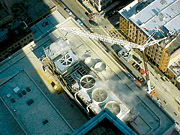
Again, the split condenser water header, normally used for economizer operation, was employed to rebuild the original five 1,000-ton condenser header to accommodate six 1,000-ton towers. A photo taken during the installation of Tower #5 clearly shows concurrent operation of Towers #1, #2, and #6, during construction (Photo 1).
Goals Achieved
After two years of operation, the plant operates flawlessly. Operator acceptance has been extremely high, an essential component of critical system reliability. Since the ME design provides redundant paths and concurrent maintenance opportunities in an intuitive manner, the plant operators have developed procedures that accommodate load shifts during extreme weather changes.Statistically, 60% of critical system failures are directly related to operator error (inappropriate responses to system requirements). At this site, the operators continuously train, without risk to the critical process, by using redundant paths as a “safety net.” Ice storms, wind, 103? weather, and dramatic increases in load have been accommodated seamlessly. Energy conservation, due to the higher efficiency chiller, variable-speed primary-secondary pumping system, and flat plate heat exchanger continue to save over $250,000 annually.
Confidence to “swing” on and off the flat plate heat exchanger, and having the ability to use the heat exchanger as either a “return water cooler” or as a “sixth chiller,” extends the operating hours and energy savings.
The savings calculations in Table 2 were before the heat exchanger was commissioned. The energy efficiency of the pumps, chillers, and cooling towers is conservatively $273,644 annually. Savings from the heat exchanger are estimated to be an additional $50,000/year.
Glass reports the following benefits from the upgrades to the plant:
- • N+2 chiller capacity;
- N+2 cooling tower capacity;
- Eliminated single points of failure;
- Increased chiller flow of 40%;
- Increased differential pressure at the data center CRAC’s 42% (from 8.8 psi to 12.5 psi);
- Chiller capacity accessed at 100%;
- Dual chilled water temperature capability (improves data center cooling efficiency while maintaining dehumification to office and trading space);
- Concurrent maintainability;
- Flexibility to divert all cooling to critical load immediately;
- Split cooling towers hot and cold sumps;
- Freeze protection;
- Controls upgrades; and
- Operating savings exceeding $250,000 annually.
