Ac drives connect to ac induction motors, and provide nearly the same capability of adjustable speed, torque, and horsepower control. To obtain full motor torque at zero speed, a special type of ac drive must be employed (e.g., direct torque control or flux vector-type systems). Those types of controls are beyond the scope of this article and would be best understood after first reviewing the contents of this article.
The Basics of Drive Application
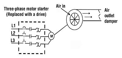
The easiest way to understand drives is to take a brief look at what a drive application looks like. Figure 1 shows a simple application with a fixed-speed fan using a motor starter. The three-phase motor starter can be replaced by a variable-frequency drive (vfd) thereby allowing the fan to be operated at variable speed.If the fan can operate at virtually any speed required (below maximum motor speed), the air outlet damper can be "fixed" open. Using the fixed-speed motor starter method, the only means of varying the air out is by adjusting the air outlet damper.

Induction Motors and Drives
Now the question is, "How does this induction motor work with a drive?As mentioned earlier, a standard three-phase induction motor can be controlled by a vfd. There are two main elements that are controlled by the drive: speed and torque.
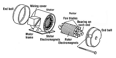
To understand how a drive controls these two elements, we will take a short review of ac induction motors. Figure 2 shows the construction of an induction motor.
The two basic parts of the motor, the rotor and stator, work through magnetic interaction. A motor contains pole pairs (iron pieces in the stator are wound in a specific pattern to provide a North-to-South magnetic field).
If one pole pair is isolated in a motor, we find that the stator magnetic field rotates at a specific speed. This speed is defined as "base speed" and is predetermined by the number of poles and the frequency applied. Figure 5 shows the formula for determining the shaft speed of an induction motor.
This formula includes a characteristic called "slip." Slip in a motor is the difference between the rotating magnetic field in the stator and the actual rotor speed. When a magnetic field passes through the conductors of the rotor, the rotor takes on magnetic fields of its own. These rotor magnetic fields will try to catch up to the rotating fields of the stator. However there is always a slight speed lag; this is called slip.

Speed and Torque
As indicated earlier, a vfd controls two main elements of a motor: speed and torque.The speed of a motor is conveniently adjusted by changing the frequency applied to the motor. As we will see shortly, the vfd adjusts the output frequency thereby adjusting the speed of the motor. (Motor speed can also be adjusted by changing the number of poles. This is typically done by reconfiguring the windings. This method is not very practical and would only provide a different constant speed.)
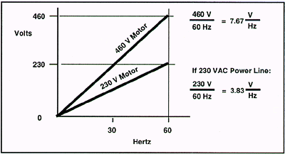
The torque of a motor is controlled by a basic characteristic of every motor - the Volts per Hertz (V/Hz) ratio.
This ratio is shown in Figure 3, and is the basic phenomenon whereby all motors develop torque.
If an induction motor is connected to a 460-V power source at 60 Hz, the ratio is 7.67 V/Hz. As long as this ratio is kept in proportion, the motor will develop rated torque.
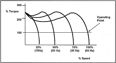
Figure 4 illustrates a typical speed -torque curve for a motor. This curve represents a motor operated at a fixed voltage and frequency source.
Changing Motor Speed
A drive provides many different frequency outputs, as shown in Figure 6.At any given frequency output of the drive, another torque curve is established. A typical operating point is where the curve intersects the 100% level, indicating rated torque.
Just how does a drive provide the frequency and voltage output necessary to change the speed of a motor? That's what we'll take a look at next.
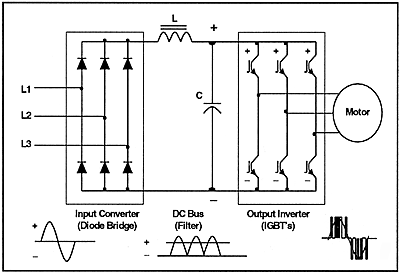
A block diagram of a basic PWM drive is indicated in Figure 7. All PWM drives contain these main parts, with subtle differences in hardware and software components.
Although some drives accept single-phase input power, we will consider the three-phase input drive. (To simplify illustrations, the waveforms in the following drive figures only show one phase of input and output.)
Three-phase power is applied to the input section of the drive, called the "converter." This section contains six diodes, arranged in an electrical "bridge." These diodes convert ac power to dc power. Because diodes are used in the converting process, the next section sees a fixed dc voltage.
The "dc bus" section accepts the now converted ac to dc voltage. The role of this section is to filter and smooth out the waveform. As shown, the diodes actually reconstruct the negative halves of the waveform onto the positive half. An average dc voltage of approximately 650 V to 680 V is seen, if the drive is a 460 vac unit (line voltage times 1.414 = dc bus voltage). The inductor (L) and the capacitor (C) work together to filter out any ac component of the dc waveform. The smoother the dc waveform, the cleaner the output waveform from the drive.
Once filtered, the dc bus voltage is delivered to the final section of the drive, called the "inverter" section. As the name implies, this section actually "inverts" the dc voltage back to ac, but in a variable voltage and frequency output. Devices, called IGBTs (Insulated Gate Bipolar Transistors) act as power switches to turn on and turn off the dc bus voltage, at specific intervals. In doing so, the inverter actually creates a variable ac voltage and frequency output. Control circuits, called gate drivers, cause the control part of the IGBT, the gate, to turn "on" and "off" as needed.
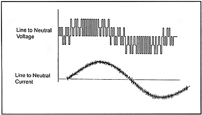
The output of the drive doesn't actually provide an exact replica of the ac input sine waveform. It actually provides voltage pulses that are at a constant magnitude in height. (The IGBTs switch the dc bus voltage "on" and "off" at designated intervals.)
The control board in the drive signals the gate driver circuits to turn "on" the waveform positive half or negative half IGBT. This alternating of positive and negative switches recreates the three-phase output.
The longer the IGBT remains on, the higher the output voltage. The less time the IGBT is on, the lower the output voltage. Conversely, the longer the IGBT is off, the lower the output frequency.
The speed at which IGBTs are switched on and off is called the "carrier frequency" or "switch frequency." The higher the switch frequency, the more resolution each PWM pulse contains. Typical switch frequencies are 3,000 to 4,000 times per second (3 KHz to 4 KHz). As you can imagine, the higher the switch frequency, the smoother the output waveform (the higher the resolution). However, there is a disadvantage. Higher switch frequencies cause decreased efficiency of the drive. The faster the switching rate, the faster the IGBTs turn "on" and "off." This causes increased heat in the IGBTs.
Future Advancements
Drive manufacturers differ in the complexity of their control circuits. However, the technology employed has come from vacuum tubes in the 1940s to full digital control in the early 1980s. As electronic power components are improved in reliability and decreased in size, the cost and size of vfd's will continue to decrease in the future.