Project Background
Approximately four years ago, in an attempt to conserve energy, a regional telecommunications provider completed a project to separate administration air-handling units (ahu) from the data center ahu. A raised floor in the data center comprised more than 150,000 sq ft. Alarmingly, humidity control and stability in the mission-critical data center deteriorated upon completion of the initial project.A critical systems mechanical diagnostic review conducted earlier this year revealed insufficient humidity control in all five floors of the data center: “holes” in the envelope. Results showed that humidifiers operating at capacity would not be able to maintain required humidity levels (35% rh) on cold winter days. Humidity control in data processing areas is especially critical because hydroscopic (moisture retaining) circuit boards expand and contract with fluctuating humidity levels. Expansion and contraction breaks microelectronic circuits and edge connectors; low humidity causes destructive static electricity discharges. In an attempt to curtail mounting costs (over $500,000 in subsequent projects and $30,000 per year in wasted energy), project managers recently hired Jack Dale Associates (JDA, Baltimore), a research and development engineering firm. JDA’s task was to quantify the amount of air transference between the data centers and their adjacent administration spaces.

Techniques to Quantify Air Transference
Air is a compressible fluid, and it can be very difficult to find defects in design, construction materials, or workmanship that allows undesired air transfer to take place. Even if the time and labor were available to find these defects, quantifying “crack infiltration” rates is tedious and unreliable, as it generally amounts to professional guesswork.Seeding an area with a tracer gas and then determining the dilution of the tracer gas that occurs from air transfer provides far greater accuracy in quantifying air transference. Since pioneering the use of this technique in 1986, JDA has continuously refined testing protocol. As an example, JDA has replaced sodium hexafloride as a tracer with less expensive “beverage-grade” carbon dioxide. It must be understood that the tracer gas is NOT carbon monoxide gas (CO), which is a harmful gas.
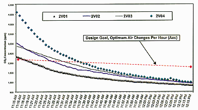
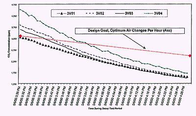
“Seeding” the space to be tested means flooding it with carbon dioxide (CO2) until the CO2 concentration in the test area reaches five times the outdoor ambient concentration (Photo 1). Data recording equipment is distributed throughout the test area. These instruments record the level of CO2 in the air at regular intervals. Data collected produces decay curves. Decay rates determine the air exchange per hour rate (Axc) of air transference.
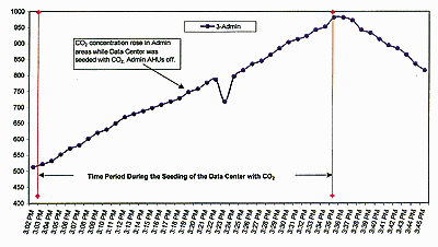
Any difference in CO2 concentration from ambient CO2 levels indicates air transference between the data center and adjacent areas. Therefore, dilution of the seeded areas in the data center indicates administration air, or outside makeup air, being transferred to the data center. The obverse is also true: if CO2 concentration increases in adjacent areas, air is moving from the data center to these spaces.
The formula for air transference follows the following differential equation:
C(t) = C’ + (Co-C’) x exp[-V(t)/Vo]
Where:
C’ = average CO2 concentration outside the test area
Co = seeding concentration level at t=0
C(t) = Concentration of tracer gas at time (t) after seeding to an initial concentration level
Vo = Volume of the area under test
V(t) = Volume of gas exchanged between the inside and outside of the space
Note: If V(t)=1 hour = Vo, then one air change has occurred in an hour then (axc = 1)
Note: Zone Volume; there are 4 ahu; each supplies 25% of the space volume
Axc = Air exchanged from the outside to the inside of the space

Environmental Parameters
Humidity requirements are directly proportional to the moisture differential between the indoor data center design conditions and the outside design conditions during cold weather. Table 1 illustrates parameters that have proven successful for our firm.These outdoor conditions are typical for the Southeast. In these conditions, adding humidity to the air would require 6.81 kW of electric humidification for every 1,000 cfm of makeup air (162,695 grains/hr). Makeup air is defined as outside air that enters into the data center directly through outside air dampers, or air that is transferred into the data center from nonhumidified adjacent spaces.
Any prudent design provides filtered and conditioned makeup air for data center environments. Excess air causes positive pressure. This prevents infiltration of dirty, unconditioned air into the center, controls airborne contamination, humidity, and temperature. Existing humidifiers in each of the four air handlers per floor total 80 kW. During a cold design day they are capable of humidifying 10,573 cfm makeup air per floor, assuming a degredation of capacity between cycles of 10%. Calculations showed that existing humidifiers are capable of producing enough steam to satisfy an air exchange per hour of 0.3 Axc.

Preliminary Findings
Existing humidifiers in each of the four air handlers per floor total 80 kW. During a cold design day, they are capable of humidifying 11,748 cfm of makeup air per floor. It is prudent to assume some degradation of capacity between maintenance cycles, so the nameplate capacity of the existing humidifiers will be reduced 10%, or 10,573 cfm. Therefore, if makeup air or air transference from adjacent spaces exceeds 10,573 cfm, the humidifiers cannot be expected to achieve critical indoor design specifications.Both floors showed construction attempts to resolve air transfer problems. Indeed, some of this work was effective. The amount of transfer between the administration and data center air handlers was negligible in the return air plenum bulkheads. Additionally, the walls between the data center and administration hallways had abandoned fire dampers that have been closed and covered with sheet metal. Field verification confirmed that the return air bulkheads and hallway demising walls were treated in a similar manner on the third floor.
Much of the data center infrastructure, however, showed evidence of successive generations of overlaid design concepts aimed at reducing air transference. Most efforts exhibited a distinct lack of scope, preparation, or cohesion with the existing system. Others appear to have caused additional problems or uncovered problems previously masked by excess capacity.
For adequate exfiltration, each floor of the facility requires 3,750 cfm of conditioned makeup air. At this quantity, the air exchange per hour would will be 0.3 Axc. Since the existing humidifiers are capable of producing enough steam to satisfy 10,573 cfm of outside air (i.e., at the proposed design conditions) modifications to the existing humidification systems should be unnecessary.

Results of Seeding
CO2seeding, confined to the second and third floors, showed that the second floor had the greatest amount of air transfer. Calculations showed 643% more air transfer than the design requirement of 0.3 Axc for floor two as compared to 430% for the third floor. Because of this, air handlers on the second floor would be incapable of maintaining required humidity levels (35% rh) year round, even in mild weather. Air handlers on the third floor would be able to maintain required humidity only into the mild winter season.Because of the air transfer on the second floor, the humidifiers require the outside air to be more humid at all times year-round than a 34˚F rainy day. The third-floor humidifiers require that the conditions outside never drop below 29˚.
The original focus of study was to determine the air transfer between the data center and administration spaces that was causing humidity control problems. The results of such a study speak to more than just humidity control problems. As mentioned earlier, availability leans on total infrastructure control. Lack of air control can allow dust and particles or even smoke to migrate into the data center. Indeed, JDA found that the excessive amounts of air transference in this case increased the risk of smoke migration. Smoke and other airborne pollutants are dangerous to the extremely sensitive microcircuits found in data centers.
