
Oil Mist Generation
Metal cutting processes typically associated with oil mist generation include those used to make metal components for engines, transmissions, and similar devices. Examples of these components are engine blocks, heads, crankshafts, camshafts, and transmission cases. Metal working fluids are applied to lubricate the cutting action, cool the tool, provide rust protection, and wash metal chips away. The metal working fluid or coolant is sprayed on the machining tool and drains by gravity to a sump or flume channel below the machine where it returns to the coolant filter system. The coolant is then cleaned and pumped back to the machining operation. There are four types of metal working fluids:
- Straight mineral oil used for honing operations;
- Soluble oil coolant that is five to 10% organic oil with the balance water;
- Synthetic oil coolant that is 95 to 98% water; and
- Semi-synthetic oil coolant that is a combination of the soluble and synthetic oils mixed with water.
Oil mist is created by the heat of the machining operation vaporizing the fluid, high-pressure sprays atomizing the fluid, and the rotating action of the tool slinging droplets into surfaces that create smaller droplets. In addition to coolants, other oils can find their way into the cutting fluid solution through leaks in the equipment's hydraulic oil system or excess lubricant from machine rails. These trap oils have a greater tendency to mist than the fluids used in coolant mixtures.
Airborne oil mist particles are considered a health concern with allowable exposure levels dropping dramatically in the future. Currently, OSHA has a limit of 5 milligrams per cubic meter (mg/m3) for an eight-hour exposure. The United Auto Workers have an agreement with major automotive OEMs to maintain a concentration below 0.5 mg/m3 for all new wet machining equipment installations. NIOSH is proposing a reduction to 0.4 mg/m3. The threshold limit value (TLV) established by the ACGIH is also currently 5 mg/m3, but they have published a notice recommending a reduction of that value to 0.2 mg/m3. Oil mist is also a housekeeping problem due to the haze in the air and slippery floors it creates.

Oil Mist Control
Over the years, local exhaust systems have been used to control oil mist. Initially, exterior hoods were applied to machining operations. This approach achieved little success since the hood had to be placed adjacent to the contaminant-generating device and draw contaminants to it by means of creating airflow into the hood. Since the part must be able to move from one machining operation to another and space is required to change/adjust tools, the resulting hood became located some distance from the operation and source of oil mist. This greatly reduced the hood's capture effectiveness and large air volumes were required to achieve any measure of success.To improve the capture of generated oil mist, enclosures were introduced to the machining equipment. An enclosing hood completely surrounds the process or the contaminant generation device. This type of hood is normally the easiest type to make perform correctly. They do the best job of all hoods in containing unwanted contaminants, but they have several disadvantages:
- They are commonly much larger and thus more expensive than exterior hoods;
- They are often an impediment to servicing and maintaining the process equipment;
- They must be kept fairly airtight to have reasonable exhaust airflow;
- They limit the ability to view the process operation; and
- They must be modified when the process changes.
An enclosing hood uses incoming air through all enclosure openings to establish an effective barrier that stops the release of the airborne contaminant into the surrounding workspace. With some enclosures, large contaminant particles are allowed to settle to the floor and are collected from below. The subject of this discussion, enclosures for oil mist control, uses this principle. Oil mist consists of small droplets and vapors that, when collected, become a liquid or metal working fluid, which can be cleaned and reused. Oil mist will collect on the machine surfaces and drain into the coolant return system. Therefore, it is not required to remove oil mist from the enclosure, only contain it.

Enclosure Design
After limited success with exterior hoods, it was determined that a hood would need to enclose the operation for good control. Initial enclosure designs were found to work quite well, but since they were not maintenance-friendly, they tended to lose their effectiveness over time. The need to change/adjust tooling, move the part in/out, and maintain the equipment made it difficult to design a hood that was integrated with these functions or had extensive removable panels. Access panels were screwed on the enclosure framework and there was a tendency for machine operators or maintenance staff to forget to reattach the panels after the machine was repaired, rendering the enclosure ineffective.Enclosures completely encapsulated the machining operation. For mass-produced products, multiple-station machines, called transfer machines, are used in the manufacture of parts where consecutive operations on a part are set side by side. The part moves from station to station as various surfaces are machined and openings created. The enclosure for a transfer machine encapsulates the entire length of the side-by-side operations with openings at each end for part movement. Part machining occurs inside the enclosure. There is a sump or flume below the point of machining that runs underneath the enclosure. Metal chips and metal working fluid or machining coolant drop into the sump or flume and are sent back to the coolant filtration system where the chips are removed and the coolant is cleaned for reuse.
In the last 10 years, machine tool builders began to integrate enclosures or guarding around the machining operations to provide a safer machine. These enclosures completely covered the part being machined as well as the machining tool - the drill, milling blade, grinding wheel, etc. Often, the drive motor is mounted outside the enclosure for better access. As enhanced guarding design evolved, the ability to contain the oil mist improved. It was discovered an enclosure that seals around the machining operation results in a quieter machine as well as one that is much cleaner, generating an insignificant amount of oil mist to the general plant environment.
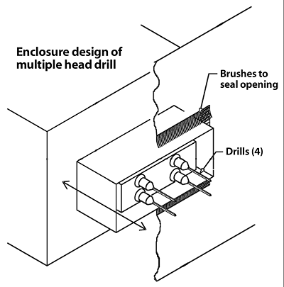
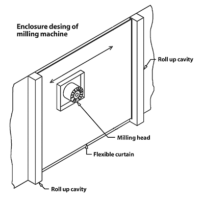
Many machines have moving parts that enable the changing of tools as well as the machining of multiple surfaces. They often have special features built into the enclosure design to reduce the total area of openings. Brushes are placed around openings where the tool indexes in and out, as shown in Figure 1. When a machine head must traverse across a part surface, the long, narrow opening is reduced by the use of metal curtains on either side of the tool that roll and unroll as the head moves, similar to a window shade (Figure 2). Access openings are hinged to provide doors that are quickly and easily closed. All these features provide a tighter enclosure that better contains the oil mist within.
Design Considerations
An enclosure can be too tight. There should be some air movement to provide ventilation inside the enclosure and to create an inward airflow when an access door is opened. There is no need to completely seal the panels that make up the enclosure with materials such as caulk or other sealers. A well-designed enclosure should have an inflow of air through the openings at 100 fpm and when the largest access door is open, the inflow should be at least 50 fpm. The lower airflow with the open door is permitted because the machining operation would be stopped and oil mist generation is minimized.To determine the appropriate enclosure exhaust airflow, calculate the total area of all openings in the enclosure. Then multiply that area by the air velocities provided above. The transfer machine enclosure has openings at the beginning and end of the machine through which the part enters and leaves. These can be shrouded or vertical plastic curtains can be used to reduce the opening area. Other open areas include those for tools to enter, cracks between the enclosure panels, the space between the machine and surface on which it rests, plus any other openings.
The exhaust system generally connects to the top of the enclosure. The velocity at these vertical connection points should be low - 800 to 1,000 fpm. This will minimize the amount of oil mist drawn into the exhaust duct system. Once the exhaust duct enters the main duct system and turns to a horizontal direction, the velocity should be increased to approximately 3,000 fpm. These ducts should be sealed, since collected oil mist droplets can combine to form larger droplets and soon can become a liquid that is capable of leaking from the duct system.
If an enclosure is too well sealed, a vent opening is advised so air can enter the enclosure. The opening is sized for a velocity of 100 to 200 fpm air velocity using the air quantity required to control emission that could escape through an open access door. This type of enclosure is found on machines making small parts and grinding operations as shown in Figure 3.
Today's transfer machine enclosure is constructed using sheet metal panels fastened to a metal structural frame. Hinged doors are used to provide access to various machine elements. The machining head of a tool can be slid back from its normal location within the enclosure to allow for easy tool changes. Brushes or some other flexible material are used to partially seal the opening with the machining head inserted into the enclosure. The transfer machine enclosure has enough openings so that no extra air relief openings are necessary. Usually, there is a need to close off extra open spaces that typically occur. These include the gap where the machine sits on the floor between the top of the flume and the chip chute. There are also openings that can be reduced in size adjacent to the machine rails. These openings do not require sealing; they just need to be blanked off so the open area is significantly reduced.
With a machine enclosure that is loosely constructed, the captured contaminant can leak out if there is inadequate inward air movement through the enclosure openings. The thermal lift of hot air could be enough to overcome a slight air movement. Generally, exhaust air is withdrawn from an enclosure at a few locations, which should be near the enclosure openings requiring the highest inflow of air. Openings that are more distant from the exhaust connections have less suction and draw in less air. In some enclosures, an internal suction distribution duct may be needed to improve the uniformity of the air inflow.


