
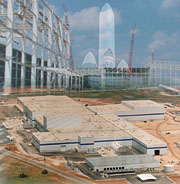
The Boeing Company, with the help of The Austin Company, has created a state-of-the-industry hvac system that controls the environment of its entire brand-new rocket factory in Decatur, AL. The facility is fully air conditioned to accommodate a low tolerance for temperature and humidity change due to thermal expansion/contraction and moisture-sensitive characteristics of the materials used to fabricate the rocket's booster core. The only air conditioning for creature comfort is in the staff office areas, which comprise a very small percentage of the overall building square footage.
The Boeing Delta Rocket Factory, completed in late December 1999, is located on 175 acres of a 410-acre site in the Mallard Fox Creek Industrial Park and Port located one mile from the Tennessee River. The rocket manufacturing factory has been designed with all the equipment and processes matched to produce Delta-class launch vehicles as efficiently as possible. The river provides a major portion of the route for delivery of the largest of these, the 165-ft-long, 16.7-ft-diameter Delta IV rocket's first stage, from the factory to launch sites at Cape Canaveral Air Station in Florida or California's Vandenberg Air Force Base.
The main structure of the $450 million rocket manufacturing facility required 7,500 tons of refrigeration, 4,000 bhp, over 2 million cfm of air, 20,000 tons of structural steel, and 100,000 cubic yards of concrete. The factory is one-half mile long and one-quarter mile wide.
The design of the rocket manufacturing facility began with developing a detailed understanding of Boeing's goals. At full production, the factory is designed to produce forty, 165-ft-long Delta IV rocket first stages each year. The facility incorporates extensive use of digital design tools and numerical machines for manufacturing accuracy, as well as a state-of-the-industry material handling system that includes 34 bridge cranes, some spanning up to 220 ft and some lifting up to 30 tons.
The rocket factory was designed for maximum efficiency with very large, open, and unencumbered floors. In order to achieve this, it was necessary to create an extensive overhead hvac distribution system and an underground tunnel and in-slab utility trench system.
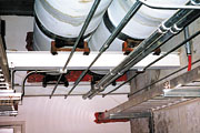
The main hvac distribution systems are located overhead in the truss space to accommodate distribution to the wide, open spaces. The truss area houses the majority of the air-handling units (ahu's) and associated ductwork and devices along with chilled water, heating hot water, and steam piping. One engineer on the project dubbed the truss area the world's largest mechanical room.
The 20-ft-deep by 20-ft-wide, approximately one-mile-long underground tunnel system was designed for emergency egress and distribution of building utility mains. The main building structure, with its massive size, required exits from the center of the building. The underground tunnel system is accessed by five ramps for small utility trucks and golf cart-type vehicles as well as a dozen stairway entrance/exits. All utilities were required to be accessible for maintenance. The tunnel utility corridor contains hvac, chilled water pipes, compressed air piping, and electrical conduits distributing power to points throughout the factory. Additionally, the utility corridors include normal and emergency power, building management and control system (BMCS) data communications, telephone, data, and fire alarm communications.
Numerous in-slab utility trenches branch off of these tunnel arteries, distributing process-specific utilities of all kinds to tooling and manufacturing equipment positions. Many of these positions were set months after the facility engineering documents were complete. The facility was also designed and constructed to allow for expansion to accommodate Boeing's future production requirements.
Hvac System and Structural Considerations
A wide range of design issues were considered in the preliminary design of the structure and the factory's state-of-the-industry hvac system. The rocket industry is a rapidly changing field; therefore, the factory had to be able to expand and adapt. A combination of steel and concrete was used to maximize the efficiency of the main structure.Large spans up to 220 ft long and steel trusses with spacing at 35 ft center-to-center were designed to carry the structure's roof system as well as to handle the loading from the 34 underhung bridge cranes and the loads from the hvac system.
The ahu's were not placed on the roof in consideration of maintenance; the climate and additional roof-structure required it to accommodate the equipment loads. The custom ahu's and their distribution ductwork were designed to integrate into the building truss system.
The trusses were also designed to provide support for all of the hvac equipment and utility distribution. The utilities include chilled water supply and return, high and medium pressure steam, steam condensate, ahu condensate, compressed air, sprinkler system piping, BMCS, and power.
The rocket factory is served by an adjacent central steam and cooling plant via an underground utility tunnel. In order to reduce summer cooling loads on the central plant, the air distribution system was designed to allow thermal stratification between the air distribution system and the roof.
A bottom-chord-level, truss-bracing system was designed to increase the stability of the roof and the truss system. Controlling deflection and vibration of the bridge crane systems was a primary concern in the design of these trusses.
The crane multirail runway systems - the rail networks that enable the cranes to provide the essential floor coverage in each production work center - are underhung at panel points from the bottom chord members of the building trusses. A one-mile-long catwalk system is used to access the truss-cavity-mounted hvac units installed on steel work platforms. The catwalk system throughout the building also provides access to platforms for servicing the various bridge crane systems.
Over 100 load cases and load combinations were used to determine the controlling structural steel member forces. The development of the dead loads, live loads, earthquake and wind loads, snow loads, ponding loads, movable loads, and impact loads is a very complex process. ENERCALC and Research Engineer's STAAD-III were the computer programs used to design the steel trusses and the catwalk system. Triflex piping system analysis and design software was used to design the piping stress analysis of the system and for the design of the pipe steel supports for the steam and condensate systems.
Trane's(r) Trace 700 was the computer program used to maximize cost-efficiency between material cost and building layout. In addition, the program was used to analyze cooling and heating loads and to predict the cost of utilities for the lifecycle cost study.

Installation and Hvac System Operation
One of the most challenging aspects of the project was the aggressive construction schedule: two years from groundbreaking to occupancy. Construction began in November 1997 and was completed in late December 1999.The crane rails were installed immediately after the erection of the building trusses. Temporary construction platforms, built from steel joists, wood, and plywood decking, were underhung from the crane rails. This innovative approach allowed the mechanical and electrical contractors to work from a platform only seven feet below the bottom of the trusses, rather than providing scaffolding or man-lifts some 70 ft in the air.
The use of the overhead work platforms enhanced the efficiency of all construction trades and allowed for a significant time reduction in the construction schedule. One of the most challenging aspects of the project included the aggressive design and installation schedule for the hvac system: the design phase was four months, while installation was only six months from October 1998 to March 1999.
The first ahu's were lifted onto their respective platforms in late October 1998 by a 400-ton crane. Air handlers were installed and commissioned to meet the Boeing schedule. Environmental control was established in the early production areas and extended throughout the construction process.
The 70,000-sq-ft central plant that serves the factory houses contains: five York R-134a centrifugal chillers; six Marley crossflow cooling towers; five Cleaver-Brooks gas-fired boilers (976 bhp each); chemical water treatment equipment; three Ingersoll-Rand air compressors (1,500 hp each); three Recold fluid coolers; and other related devices and appurtenances. The systems maintain ample redundancy as well as room for growth.
The primary heating media for the factory comes from high-pressure, 125 psig steam delivered through a 14-in. main in the utility tunnel section between the central plant and the factory and climbs out of the tunnel into the truss space inside the manufacturing plant. Two hundred degree Fahrenheit hot water to heat the building and temper outdoor air is generated from steam-heat exchangers and circulated by variable-speed pumps to the ahu heating coils. Steam-pressure-powered pumps return pumped condensate to the central plant in a 6-in. main located in the utility tunnel.
The cooling media includes process and factory cooling. Factory cooling consists of 40° chilled water circulated by 30-in. piping routed in the underground tunnel. A primary, constant-flow pump-chiller loop configuration was implemented at the central plant. Five 75-hp variable-speed pumps arranged in parallel produce a constant flow for optimum equipment efficiency at a temperature differential of 20°. As chilled water demand increases, additional pump-chiller sets operate up to a current total capacity of 7,125 tons. Pressure and temperature sensors installed at the end of the distribution circuit provide differential pressure and supply temperature input to accurately adjust chiller and pump output to supply only what is required.
The rocket factory is divided into separate zones with individual space requirements for humidity control and ventilation. The ahu's are located above the factory floor at the roof truss level with service access via an extensive catwalk system.
Close coordination was required with the erection of the structural steel framing of the building in order to lift and set the 62 ahu's on platforms prior to completion of the roof. The Temtrol constant and variable-volume (vav) air handling units range in capacity up to 45,000 cfm, capable of 100% outdoor air, with hot water preheat, chilled water cooling and hot water reheat coils, prefilters, final filters, and oil-mist eliminators. Duct systems were coordinated in critical areas to maintain tight clearances with the extensive crane rail transport support steel.
Greenheck centrifugal fans meet exhaust requirements throughout the plant with exhaust volumes up to 17,000 cfm. Centrifugal roof exhausters and inline cabinet, axial upblast, tube axial, and propeller fans were all employed in ventilation of these zones.
The entire hvac system is controlled via a direct-digital-control building automation system. Automated Logic Corporation was chosen for the ease of interoperability with the various control subsystems and the use of BACnet protocol.
A central workstation running building management software monitors the factory network and downloads programming changes or initiates alarm sequences as required.
With early move-in dates, all primary mechanical equipment had to be operable by the first scheduled date. Specific systems had to be commissioned to provide the necessary hvac, plumbing, electrical, and fire protection serving those occupied spaces. This meant scheduling an early punchlist and system start-up and providing operating instructions, record drawings, and operation and maintenance manuals at an early date.
Project Team
The Austin Company provided the design and engineering services for the entire Delta Rocket Manufacturing Facility. Construction was performed by Austin-Alberici, a joint venture between The Austin Company and J.S. Alberici Construction Co. Inc.Two contractors were involved in the construction and the installation of the hvac systems: Stanley Jones Corporation (Birmingham, AL) and McAbee-Murphy, the Joint Venture of McAbee Construction Inc. (Tuscaloosa, AL), and The Murphy Company of (St. Louis). The Comfort Group (Nashville, TN) installed the BMCS, and Systems Analysis Incorporated (Birmingham, AL) performed the test and balance. The prepurchased hvac equipment was manufactured by the following: steam boilers by Cleaver-Brooks, water chillers by York International, cooling towers by Marley Cooling Tower, and custom ahu's by Temtrol.
The structure's truss system, the hvac platforms, and the catwalk access system were fabricated by the tri-venture team of AISC-members Havens Steel of (Kansas City, MO); Qualico Steel of (Dothan, AL); and Hillsdale Fabricators of (St. Louis). The erection team consisted of Hillsdale Fabricators and AISC-member National Riggers of Detroit.
The 20th century has seen extraordinary strides in building materials, design concepts and methods, and construction practices. The challenge of the new century will be the in-depth coordination and enhanced communication among the many members of a project team for cutting-edge time management. Communications on this project were greatly enhanced by the use of an extranet and e-mail. The design-build team managed to finish the installation of the hvac system on schedule, within the project budget, and with a quality and safety record well above industry standards. ES
