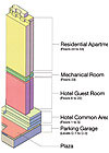
FIGURE 1. A building outline of 839 Avenue of Americas.
A 53-story Chelsea building must meet a towering array of life safety code requirements for its various spaces. Elsewhere in Manhattan, a nondescript command center requires heavily integrated fire/smoke control, security, and HVAC systems. And a Brooklyn data center wanted a more modern fire suppression approach but faced a code that required sprinklers. Whether literally high-profile or intentionally anonymous, NYC projects and their owners are navigating a maze of constraints while keeping the fundamental goal in sight.
Mixed-Use In Manhattan
As increasing numbers of mixed-use buildings appear in the Big Apple, they must clear significant hurdles to meet life safety codes. With these combinations of hotels, apartments, and retail/commercial components sharing a roof and structural elements, what HVAC or life safety design adjustments must be made?
In 2006, J.D. Carlisle Development Corporation began plans to erect a 53-story mixed-use tower at 839 Avenue of Americas, between 29th and 30th Streets in New York City. Engineering a mixed-use tower of this magnitude, with a façade of over 50% glass window-wall and with separate hotel and residential life safety and mechanical systems, proved to be a challenge.
Moving On Up To A Deluxe ...
The 600,000-sq-ft mixed-use tower will be located in Manhattan’s Chelsea neighborhood and will include four stories of below-grade parking, 22 stories of hotel/guest rooms, and 30 stories of residential apartments. A public, landscaped urban plaza will connect West 29th and West 30th Streets and serve as an alternate entrance into the hotel and restaurant.Perkins Eastman Architects PC leads the team of over 15 consultants and subconsultants, including Dagher Engineering PLLC, who is providing engineering services through all phases of development design and construction (involving all MEP, sanitary, fire protection, and life safety design). The 287-room hotel and 291 apartments are scheduled to open in 2009.
The mechanical and electrical space located above the hotel tower (floors 1 to 22) contained an 18-ft, floor-to-floor ceiling height dictated by the hotel elevator bank overrun and traction mechanical room. This large 8,000-sq-ft footprint located on the 23rd floor was used to house separate hotel and residential mechanical systems. A two-tier design was used to contain five Cleaver Brooks boilers, one Multistack modular chiller, five PVI heat exchangers for domestic hot water storage, 13 high-efficiency Armstrong water pumps, 20 Greenheck fans, five Armstrong expansion tanks, two Armstrong plate-and-frame heat exchangers, one Armstrong shell and tube heat exchanger, two pneumatic cushion tanks, five domestic water Therm-x-Trol expansion tanks, over 700-sq-ft of louver area, and over 500 ft of ductwork and piping.
Apartment HVAC
The residential mechanical HVAC system was initially designed as a waterside heat pump system similar to the hotel design. However, a shift in the real estate market during the design process triggered the owner to switch from high-end luxury condos to a more efficient, moderate apartment design.Several mechanical systems were considered for the apartments. Steam baseboard and hot water baseboard systems were some of the many options, but they were eliminated due to cost, possible excessive maintenance, and the owner’s requirement to maximize the glass area in each apartment.
In the end, A/C and heating for the 291 residential units was provided by a two-pipe hot/cold water system using both console and vertical fancoil units. The water supply is switched seasonally from the 23rd floor mechanical room to provide hot or chilled water.
In the summer, chilled water is provided by a Multistack 300-ton, air cooled modular chiller located on the 53rd floor roof. Each module uses multiple 15-ton compressors to avoid the requirements of a stationary engineer for the building.
In the winter, two dedicated Cleaver Brooks flexible watertube gas-fired, 167-bhp boilers provide heat to the fancoil unit system. The 250,000-sq-ft residential tower (floors 24 to 53) has approximately 62% glass-window wall, therefore in order to maintain thermal comfort, all vertical and console fancoil units are located at the perimeter of the residential apartments.
International Environmental vertical and horizontal fancoil units were specified for the residential space. The location of the fancoil unit along the perimeter of each apartment allows the air to discharge across the large area of glass, providing maximum comfort for the occupants and maximizing the views.
Hotel HVAC
The 287 hotel rooms are air conditioned and heated by individual room horizontal ceiling water source heat pumps by Climatemaster. A 600-ton, Evapco two-cell, evaporative cooling tower located on the roof will provide heat rejection (cooling) for the heat pump units. The cooling tower plant and water circulating pumps were sized based on the building peak “bulk” load using Trane’s TRACE software.Three dedicated Cleaver Brooks flexible watertube 167-bhp, gas-fired boilers provide supplemental heat to the hotel’s heat pump condenser water system in the winter. The hotel heating and cooling systems are designed to maintain comfort conditions that comply with the New York City Building Department Code and the New York State Energy Code.
Express hot water supply and return risers provide hot water to the AHUs, which serve the lower floors as well as air curtains on the first level garage for tempering of makeup air for the garage exhaust system.
Two smoke purge fans located in the ceiling of the third floor serve floors 2 to 5 of the hotel. The first floor lobbies and retail areas have individual smoke purge fans to allow for the separation of occupancies within the first floor. All smoke purge fans are sized for the code-required 6 ach of floor volume and are integrated into the fire alarm control panel in the main level lobby.
In Common
The hotel and residential common areas on floors 1 to 5 will be air conditioned by ceiling hung McQuay AHUs located in the ceiling areas of the back of house and on interstitial mezzanine areas between floors. A combination of fan-powered boxes and VAV boxes downstream of the AHUs are zoned for particular heating and cooling requirements of the individual rooms on the lower floors.Chilled water to the AHUs is provided by a dedicated Multistack 300-ton, water cooled chiller located in the 23rd floor mechanical room. The chiller waste heat will be rejected to a plate and frame heat exchanger located in the mechanical chiller room to an evaporative cooled 600-ton condenser water loop. The open tower condenser water loop will be isolated to the chiller closed loop because of water treatment and high-pressure concerns. Waterside economizers will provide free cooling in the winter season.
The OA ventilation requirements for both the hotel and residential units are met by means of natural ventilation through operable windows. All interior public corridors and common spaces are mechanically ventilated by separate rooftop or air cooled A/C units. All studio apartments are also mechanically exhausted by a centrifugal roof or utility exhaust fan located on the 23rd-floor mechanical room.
The occupancy classification of the hotel according the New York City Code is J-1, which requires a smoke control mechanical system of 6 ach for the largest hotel floor. Two smoke exhaust shaftways are located along the hotel portion of the tower and are connected to a dedicated fan system located in the 23rd-floor mechanical room. The four stories of below-grade parking are served by individual supply and exhaust shaftways for each floor. The system is also tied to a CO2 detection system that mechanically controls the exhaust and supply fans.
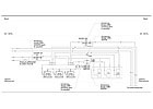
FIGURE 2. Hotel/restaurant mechanical system.
Mixed-Use Challenges
Several challenges unique to this mixed-use building were presented through design constraints, which were addressed by Dagher Engineering working closely with Perkins Eastman Architects, Kimpton Hotels, Philip Koether Architects, McCarten, and Titus Air Management. These difficulties, although not unique to the industry, nevertheless presented an interesting approach to the building’s HVAC requirements.The criteria for the hotel public areas (restaurant space, ballrooms, pre-function rooms, etc.) mandate full floor-to-slab glass heights without the use of perimeter radiation at the base of the glass façade. The average floor-to-floor heights are 16-ft with 12-ft high soffits approximately 2.5 ft from the glass façade.
Titus recommended the “Dyna-Fuser,” a linear air diffuser able to provide a vertically projected airstream during the heating season and a horizontal airstream during cooling season. To minimize stratification of the airstream, a terminal velocity of 150 fpm at approximately 4-ft, 6-in. above the floor is used during the heating season.
In order to cover the upper portion of the glass with warm air and prevent condensation from occurring during the heating season, a linear return slot or opening is placed at the upper portion of the ceiling soffit. To prevent airstreams from converging and dropping at the corners of the rooms where linear diffusers meet at right angles, one section of the linear diffuser will be set in a fixed vertical projection. The use of fan-powered boxes will allow for a constant airflow across the glass surface to reduce temperature gradients and drafts, and prevent stratification of the room air.
The hotel guest rooms’ design includes full floor to slab glass heights without the use of perimeter radiation at the base, sidewall, or ceiling of glass façade. Perkins Eastman Architects will provide a soffit ceiling within the hotel rooms at a maximum distance of 12-ft from glass façades. Working closely with Titus, certain design methods and parameters were developed to achieve thermal comfort for the occupants of the space.
To obtain longer horizontal throw distances, the Coanda Effect will be used, causing the airstream to become attached to the ceiling and reducing air induction. To use this effect, the top of the supply grille is designed to be within 6-in. of the ceiling. A secondary result of using the Coanda Effect is that airflow will continue along the surface of a wall after traveling along the ceiling, if the end of the room is reached with negligible momentum loss to the airstream when altering directions. This will allow the airflow to continue vertically down the glass after traveling along the ceiling.
Unlike the hotel common area that used a terminal velocity of 150 fpm, a terminal velocity of 125 fpm at approximately 4-ft, 6-in. above the floor was used during the heating season. This is due to decreased airflow temperature gradients and buoyancy as the airflow induces room air while traveling along the ceiling.
Having the airflow reach this distance from the ceiling will minimize stratification of room air. In order to meet all design parameters, a side wall supply grille with 22º horizontal deflections located within 6-in. of the ceiling was used for heating and cooling applications in hotel guest rooms. Manually controlled three-setting fan speed switches are provided to allow hotel guests the opportunity to increase fan speed in winter, which will increase airflow throw values, and decrease fan speed in the summer, which will reduce potential drafts.
Life Safety System Design
The life safety systems designed are unique to meet the demands of the New York City Building Code, the NFPA, and the International Building Code. Meeting the latest design requirements, while delivering a code compliant structure, was a challenging experience.Dual 6-in. fire services are supplied to the building from West 29th and West 30th Streets. Detector check valves are located at the foundation wall(s) to meet the requirements for backflow prevention. The services then cross connect and supply a 750-gpm manual fire pump that will serve the entire structure and a 500-gpm automatic fire pump serving the hotel portion only. In addition, New York City Fire Department Siamese connections are located on all streets and tie to the pump discharge(s).
The fire reserve for the Residential Tower is supplied from a 5,000-gal reserve tank located at the roof level. This tank is filled by a dedicated set of duplex fill pumps located in the C-1 garage level
The “High Zone” portion of the Residential Tower is supplied from a 500-gpm special service fire booster pump located in the fire reserve tank room on the roof. This pump supplies the residential sprinklers until the gravity pressure from the tank reaches 60 psi and can take over. Six-in. combined sprinkler/standpipe risers are supplied in the stair, and sprinkler valve rigs are complete with tamper and flow switches tied to the building’s fire alarm system on all floors.
There is a separate sprinkler supply riser for the trash chute in the Residential Tower. The design criterion for the residential tower is light hazard occupancy. All mechanical room spaces are designed for Ordinary Hazard “Group-1,” and sidewall sprinklers are provided where possible in the apartments to maximize ceiling heights.
The hotel portion of the tower has a dedicated 500-gpm automatic fire pump to supply only the lower 300 ft of the building. The pump is designed to supply a minimum 60 psi at the upper most floor of the hotel. A 6-in. combined sprinkler/standpipe riser is supplied for the hotel, along with a dedicated 6-in. standpipe riser and separate laundry chute riser.
All sprinkler control valves are provided with tamper and flow switches as required by NYC building code and wired to the building’s “Class-E” fire alarm system. Design criteria for the hotel sprinklers will be light hazard for guest rooms and corridors and Ordinary Hazard Group-1 for all mechanical equipment rooms, loading dock area, and retail spaces.
In addition, fire supply risers are provided with sectional control valves and pressure reducing valves where required to meet the maximum pressure code restrictions. All fire standpipe riser piping is designed to meet the pressures within each zone.
The four lower garage levels are supplied from the hotel automatic fire pump and are designed with a dry type sprinkler system. Individual (heated) dry-pipe valve rooms are located on each of the garage levels, and all dry sprinkler piping is galvanized steel. All below-grade levels are designed for Ordinary Hazard Group 1 with upright sprinklers throughout.
Fire Alarm System Design
The fire alarm systems designed for this combination hotel, restaurant, four-level below-grade garage, and residential tower are separated to meet the requirements of the New York City Electrical Code, New York City Building Code, and especially the demands the of the New York City Fire Department. The hotel, restaurant, apartment, and garage fire alarm systems will communicate and be integrated to each other to monitor trouble conditions to the other portions of the building.The systems are also backed up by an emergency generator and battery power sources. The hotel portion will have a “Class J” system with voice evacuation and fire fighters’ telephone system, which annunciates a fire alarm condition to guests in the building and allows communication points for firefighters throughout the hotel portion of the building as an alternative option if their communication system is interrupted.
Data Center Health Is A Plus In Brooklyn
Health Plus is one of the fastest-growing managed care organizations in New York City. Established in 1984 by Lutheran Medical Center (LMC) to provide coordinated quality health care and improve access to care for a diverse and growing number of uninsured New Yorkers in Southwest Brooklyn, Health Plus now serves the five boroughs of New York and Nassau County and covers nearly 270,000 members.
With 15 offices around the state wired into the main data center at its Brooklyn main hub, the organization needed a fire protection system in their main computer server room, which serves as the backbone of the company’s business and ties together all affiliated branches. Downtime is not an option for this critical center located in a five-floor, multi-tenant building, which is monitored 24/7/365.
Health Plus officials sought bids for this process and ended up selecting Simplex Grinnell and Ansul Incorporated to provide a system to automatically detect and suppress any potential threat of fire. Work on the project began in mid-September 2007, and as this article went to press, the final phases of construction to seal the space and modify the purge exhaust system were being completed.
Fire Protection Footprints
Originally, two clean agent fire protection systems were considered: the ANSUL® INERGEN® System and HFC 227 EA. INERGEN is an environmentally friendly fire suppression solution with no atmospheric lifetime and zero ozone depletion. It extinguishes a fire by lowering O2 levels to where combustion cannot be sustained (greater than 15%).However, according to Luis Gonzalez, Regional Special Hazards representative for SimplexGrinnell LP, in this case the footprint of the ANSUL SAPPHIRE® system was better suited for Health Plus’s available floor space than INERGEN. “Because Health Plus occupies only two floors of the building, SAPPHIRE’s smaller footprint made it the preferred solution for this project,” he said.
Since SAPPHIRE uses Novec 1230™ fire protection fluid, it was the system of choice because of its environmental impact as well as its physical footprint. The system provided Health Plus with an effective solution to meet their fire protection needs, and saved valuable real estate.
Of course, local fire protection codes mandate what is acceptable for use in protecting a building’s data center and what is not. The New York Fire Department is the AHJ, and as such requires sprinkler systems in all commercial buildings of this size and occupancy rating.
The building is sprinklered and has a fire alarm system installed throughout. However, the release of water from a sprinkler system would present a critical disruption to the operation of Health Plus’s business. Therefore, the intent was to protect the critical nature of their computer equipment with a smoke detection system that was coupled with an automatic SAPPHIRE System.
Removing the sprinklers from the protected space required petitioning the NYC Building Department for a variance. After several months, the variance was granted as long as main and reserved SAPPHIRE systems were installed.
The SAPPHIRE system notifies Health Plus of any potential problems within the protected space, and during non-manned hours would discharge automatically during the earliest stages of a fire to limit a potential disruption, said Gonzalez.
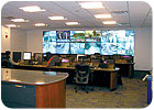
The Security Center has the capability to monitor access control,CCTV, and intrusion alarms for all Con Edison facilities.
An Integral Part
The interface between the SAPPHIRE System and SAPPHIRE’s HVAC equipment is an integral part of the design of the system. The automatic or manual activation of the system is set in motion by the activation of either a combination of two smoke detectors (known as cross-zone activation), or by the operation of an emergency manual pull station. Audible and visual alarms immediately operate to notify the occupants of an imminent problem within the protected space. This gives tenants an opportunity to investigate or evacuate and allow the extinguishing gas to do its work.Additionally, in accordance with NYC Codes, a dedicated duct was provided for purge exhaust per NYC code. Fortunately, there was ductwork already in the space that could be used for this purpose. A modification to the ductwork with the addition of a couple of dampers will allow the balance of the space to be properly interlocked. And with all of these measures taken, the Health Plus staff rests easier knowing the backbone of its business is properly protected.
Power To The People
Consolidated Edison Company of New York (Con Edison, a.k.a. Con Ed), provides electric, gas, and steam distribution to 9 million people in the region, including 3.2 million electric customers, in addition to more than 1 million gas customers and 1 million steam customers in Manhattan. Along with the demands of powering the Big Apple comes the responsibility of maintaining those power supplies and securing them from sabotage, natural disasters, and other causes of outages.
After the 9/11 attacks and the Northeast Blackout of 2003, Con Edison Corporate Security decided, with guidance of the New York State Public Service Commission, to establish an operations center for the entire Con Edison Corporate Security structure. It was a joint effort between the company’s Engineering, Construction Management, and Corporate Security departments and Caltron Security Services Corp., a Queens, New York-based security vendor.
“After the 9/11 impact, every system in New York City got evaluated, and since our system is so sensitive and needs to be operational 24/7/365, it was no exception,” said Scott Gross, systems specialist with the Con Edison Corporate Security Department. The project’s initial design started three years ago.
Location, Location, Location
The utility’s Facility Management and Facility Engineers departments tackled a good chunk of the design and specification (including the mechanical systems) in conjunction with the Corporate Security department. Since security is of the utmost importance, the building needed to be as anonymous as possible.“The location is not in an urban center, so other challenges that would be faced with skyscrapers, etc., were not present,” said Gross. While there wasn’t a concerted effort to make the facility green per se, the fact that it’s in a recycled warehouse-type building that’s roughly a century old was appealing. The building’s structure also lent itself to easy ducting and cabling with its open ceiling, and it’s also centrally located for optimum communications, both internal and external.
The 2,400-sq-ft (roughly) center was slated for completion in early December 2007, and as this article went to press, its massive video wall installation was proceeding as well as connection to all the utility’s facilities. The center will have the capability to monitor access control, CCTV, and intrusion alarms for all Con Edison facilities in the five boroughs and Westchester County. It will also have the capability to monitor intrusion/perimeter alarms, BMS systems, and in the future, fire alarms throughout entire corporate structure. The command center's signals are received by a Keltron Corporation head end.
The center basically consists of a LAN room, which is essentially its computer or data center, and the general control room. The center’s fire alarm system was designed internally by the engineering staff and then approved by the AHJ. A Pyrotronics MXL system was zoned to provide notice of an incident occurring in LAN room including the ceiling, above ceiling, and below the raised floor, and included duct detectors.
The center receives redundant signals via Con Ed’s LAN, WAN, and dedicated telephone lines and has direct communications with all local emergency agencies. Redundant times-two diesel generators back it, and the LAN room is supplied by a UPS.
The LAN room is protected by a Halon fire suppression system, and the entire building is equipped with an evacuation system, all of which were supplied by Pyrotronics and System Sensor.
Keeping It Cool
Both the LAN room and the control room have split-type A/C systems (interior AHUs and exterior condensers), according to Don Azzolini, section manager of facilities engineering, who’s responsible for facilities at all the utility’s commercial buildings.In the LAN room, a ductless system was the way to go, Azzolini said. “We selected a Liebert system, and we wanted to go ductless. It was a small enough room where you can just pump the air in there, and it handles it just fine,” he added.
The 3-ton Liebert units each have the capacity to serve the room while the other serves as a backup. Azzolini said that since the building was so open in terms of walls and ceiling the installation was very straightforward.
In the control room, two Lenox 8-ton ducted split systems were deployed. Azzolini said that since there was already electric infrastructure in place along with a diesel generator with enough capacity to serve the control room, they just had to tap into them.
In total, Con Ed has approximately 100 buildings (facilities), including offices, work locations, substations, and control centers. Knowing they are all tied together and that the unifying system has proper HVAC protection is key since Con Ed customers are using 20% more electricity than they did 10 years ago, and estimates suggest demand will rise another 10%-15% in the next decade.
Commanding Attention
Major incidents, such as the 9/11 attacks, propelled physical security to the top of the list of building design priorities. That effect was more noticeable in New York City than any other place, where the impact of 9/11 was the highest, coupled with its sheer number of high-rise commercial buildings and the heavy presence of financial institutions.
Mohammed Atif Shehzad is security group manager for Constantin Walsh-Lowe, LLC, an IT consulting firm based in Jersey City, NJ, with offices in Boston, Chicago, San Francisco, and London. According to Atif Shehzad, one of the main lessons learned from 9/11 was the importance of accountability of staff and visitors inside an office space. “It was now not only important to secure a building, but also equally important to know how many people had gone inside, how to locate them, and how to account for them as they safely evacuated,” he said.
This was a key concept when Constantin Walsh-Lowe was commissioned by a client (who preferred to remain nameless in this article) to design a new security command center in their headquarters office in New York City. The vision of the command center was laid out as the central hub for all security and life safety monitoring for the New York City headquarters and 57 future offices worldwide. The project also included use of fire stairs for interfloor travel, which has become an increasingly common trend in New York City and other cities with high-rise commercial buildings.
Stairing At An Integrated System
Walsh-Lowe initially viewed the project as an integrated solution involving technology, alarm monitoring, and business policy. “In order to provide a single source of monitoring for all of their offices, we needed to provide maximum integration across various systems, including HVAC,” Atif Shehzad said.The core of the monitoring environment remained physical security and access control. However, a key component was also monitoring life safety and building systems. In order to develop a robust solution, the client, Constantin Walsh-Lowe, and Security Services and Technologies (SST), the security systems integrator, initiated several new pilots to test emerging technologies in the field of physical security. These included CCTV surveillance systems, building systems monitoring, video wall and command center solutions, and integrated and automated policy engines.
Upon completion of pilot testing, selected manufacturers were then specified and commissioned to implement the envisioned solution. For life safety and the BMS, the following standards were developed:
- Temperature, humidity, and water sensors in security data centers to monitor temperature and humidity of the room, chiller basins for water leaks, UPS power activation, and battery status.
- Live monitoring of the building systems’ alarms in the new security command center, coupled with an integrated policy to report alarms to the proper engineering groups.
- Integrated GUI showing locations of physical alarms, with priority on each alarm.
- A threshold was set to prioritize alarms vs. warnings vs. indications.
- A CCTV camera in each room, integrated with the command center. The camera would activate the instant an HVAC alarm was activated. This would allow the security staff in the command center to view the conditions inside the room before having to dispatch anyone, thus saving time and making the proper decision on whom to dispatch with certain instructions.
In addition to the HVAC monitoring of critical security rooms, the project also focused on stairwells being used for interfloor travels. Both security and life-safety concerns were a factor for staff traveling inside the stairs. The stairwells were equipped with access control, fully integrated with the fire alarm system.ES
