
Figure
1. Water cooled chiller
diagram.
That pretty much covers it. You know, design options, performance standards, part-load values, operating factors, and more. Use it as a quick brush-up, or pass it along as a handy reference.
With over 80,000 operating units in North America, chillers are the cooling workhorses for many commercial and industrial facilities. There are two primary chiller types: absorption and refrigerant, which operate very differently. This article will focus on refrigerant chillers.That pretty much covers it. You know, design options, performance standards, part-load values, operating factors, and more. Use it as a quick brush-up, or pass it along as a handy reference.
There are two primary types of refrigerant chillers, either air cooled and water cooled condenser with either scroll, screw, or centrifugal compressors. Also, a number of design variables affect chiller design, selection, and performance, including chilled water supply and return temperatures, percentage of chilled water glycol, condenser water supply and return temperatures, refrigerant-type used, chilled water system part-load requirements, chiller installation altitude, sequence of operation requirements, and available electrical service. These and other factors make refrigerant chillers the most complex piece of HVAC equipment.
This article’s goal is to provide the reader with a basic refrigerant chiller description, applicable chiller performance standard, normal operating parameters, and information on chiller operation outside of normal operating parameters.
Refrigerant Chiller Description
Refrigerant chillers follow the Carnot Cycle, which has four main steps (Figure 1): compression (compressor), condensing (condenser), expansion (expansion valve), and evaporation (evaporator). Note the chiller has a high-pressure side (from compressor through condenser to expansion valve) and low-pressure side (from expansion valve through evaporator to compressor).Most scroll and screw chillers have available options but are not considered custom-made machines, while centrifugal chillers are typically custom-designed and built, giving the designer substantial flexibility. The following component descriptions will include some available options and standard operating parameters:
Evaporator.The evaporator is where the refrigerant removes heat (energy) from the chilled water. The evaporator can be a brazed-plate-frame heat exchanger (smaller scroll and screw chillers) or a shell-and-tube heat exchanger. The two shell-and-tube evaporator types include DX barrel (refrigerant runs through tubes and water runs through shell) and flooded (water runs through tubes and refrigerant runs through shells).
To ensure good heat transfer between the chilled water and refrigerant, it is important to maintain turbulent chilled water flow. The recommended minimum chilled water flow velocity is 3 feet per second (fps) to prevent laminar flow, and the maximum chilled water flow velocity is 12 fps to prevent pipe erosion. Evaporators come in one, two, or three passes configurations with the number of passes being dependent upon chilled water temperature difference and manufacturer’s standard product (Figure 2).

Graph
1. Part load energy usage.
Condenser.The condenser is where the refrigerant rejects heat (energy) to the condenser water or air, causing refrigerant phase change from gas to liquid. There are three condenser types: water cooled, air cooled, and evaporative cooled. Most chillers utilize water cooled or air cooled condensers, and these two condensers are discussed.
-
Water
cooled condenser. Water
cooled condensers typically involve a shell-and-tube heat exchanger
with condenser water running through the tubes and the refrigerant in
the shell space. The condenser water flow must have the same flow
velocity range as the evaporator, 3 fps to 12 fps. Water cooled
condensers come in one-, two-, or three-pass configurations with
similar water entering/leaving temperature differentials as chilled
water. A standard water cooled condenser is rated at 85° ambient
outdoor air temperature but performance data is usually provided for
65° and 75° ambient outside air
temperature.
-
Air
cooled condenser.
The air cooled condenser is where the refrigerant rejects heat
(energy) directly to the outside air. Air cooled condensers can be an
integral chiller component or be a remote condenser with refrigerant
piping connecting it to the chiller. The air cooled condenser is a
coil(s) having copper tubing with aluminum fins and condenser fan(s).
A standard air cooled condenser is rated at 95° ambient outside
air temperature, but performance data is usually provided for 105°
and 115° ambient outside air temperature.
Compressor.The compressor is the chiller system’s heart. It takes the lower-pressure vaporized refrigerant coming out of the evaporator, compresses it to a higher pressure, and discharges it into the condenser. Chiller systems utilize two types of compressors, positive-displacement and dynamic. Positive-displacement compressors physically compress the vaporized refrigerant into a smaller volume and higher pressure, and include reciprocating, rotary, and orbital types. The two most utilized positive-displacement compressors are the scroll and rotary screw. A centrifugal compressor is the most utilized dynamic compressor. Dynamic compressors increase vaporized refrigerant pressure by the kinetic energy imparted on refrigerant by a rotating impeller.
Each compressor type’s method of operation, advantages, available chiller capacities, and energy usage range are as follows:
-
Scroll
compressor. The
scroll compressor is a positive displacement machine that consists of
two interleaved scrolls (Figure 3). One scroll is stationary while
the other scroll orbits eccentrically, compressing the refrigerant.
The scroll compressor’s advantages include fewer moving parts,
quieter operation, and compact size. The scroll compressor’s
high-tolerance machining requirement limits the scroll cooling
capacity to 30 tons or less. Air cooled scroll chillers are available
with cooling capacities between 10 tons and 190 tons and energy usage
between 1.1 and 1.5 kW/ton. Water cooled scroll chillers are
available with cooling capacities between 30 tons and 120 tons and
energy usage of 0.7 and 0.9 kW/ton.
-
Rotary
screw compressor. The
rotary screw compressor is a positive displacement machine that
consists of either a single or twin screw(s) (Figure 4). The screw(s)
rotate to compress the refrigerant into a smaller volume, raising its
pressure. Screw compressor advantages include higher reliability,
compact size, and tighter chilled water temperature control (+0.5°F).
An individual screw compressor has a cooling capacity of 200 tons or
less. Air cooled screw chillers are available with cooling capacities
between 80 tons and 500 tons and energy usage between 1.1 and 1.5
kW/ton. Water cooled screw chillers are available with cooling
capacities between 70 tons and 265 tons and energy usage between 0.65
and 0.9 kW/ton.
-
Centrifugal
compressor. The
centrifugal compressor is a dynamic machine that includes an impeller
(Figure 5). The spinning impeller transfers its kinetic energy to the
refrigerant, raising the vaporized refrigerant’s pressure. The
critical variable for centrifugal compressors is the impeller tip
speed, which must be maintained regardless of chiller loading.
Centrifugal compressor advantages include larger capacity chillers,
lower energy usage, multi-stage compression, and higher reliability.
An individualcentrifugal compressor has a cooling capacity of
2,000 tons or less.
Centrifugal chillers are water cooled and are available with cooling capacities of 200 tons to 2,000 tons for a single-compressor centrifugal chiller, and 400 tons to 4,000 tons for a two-compressor centrifugal chiller. Centrifugal compressor chillers are the most energy efficient chillers with energy usage between 0.5 and 0.6 kW/ton.
-
Expansion
valves.
High-pressure liquid refrigerant passes through expansion valves,
reducing pressure and flashing to a gas within the evaporator,
absorbing energy from the chilled water. Expansion valves range from
a simple orifice opening in the pipe to a complex modulating valve
that provides dynamic load control.
-
Refrigerants.
Refrigerant technology is changing because production of
several commonly used refrigerants will soon end, including R-22 in
2010 and R-123 in 2020. However, refrigerants should be available for
the life of R-22 and R-123 chillers purchased today.
Refrigerants come in three classifications: high pressure (R-22, R-407C, and R-410A), medium pressure (R-134A), and low pressure (R-123). The high-pressure and medium-pressure refrigerants are utilized in positive-displacement chillers, and the medium- and low-pressure refrigerants are used for dynamic chillers. Scroll chillers typically use R-22, R-407C, or R-410A refrigerants. Screw chillers typically use R-134A or R-407C refrigerants. Centrifugal chillers typically use R-123 or R-134A refrigerants.
Graph
2. Chiller capacity vs. condenser entering water temperature.
Chiller Performance Standard
ARI Standard 550/590 is the primary performance standard for screw and centrifugal chillers up to 2,000 tons, though many manufacturers interviewed for this article utilized ARI Standard 550/590 for rating their water cooled scroll chillers, air cooled scroll chillers, and air cooled screw chillers. This standard provides a testing protocol for determining the chiller capacity (tons), energy usage (kW/ton), fluid pressure drop (ft of water), and integrated part load value (IPLV) or non-standard part load value (NPLV).The standard has established testing criteria for performing the testing, including:
Graph
3. Chiller energy usage vs. condenser entering water temperature.
- Leaving
chilled water temperature: 44°
- Evaporator
waterside fouling allowance: 0.0001
- Chilled
water flow rate: 2.4 gpm/ton
- Entering
condenser water temperature: 85°
- Condenser
waterside fouling allowance: 0.00025
- Condenser water flow rate: 3.0 gpm/ton
Graph
4. Chiller capacity vs. chilled water temperature difference.
A = kW/ton at 100% capacity (condenser water at 85°)
B = kW/ton at 75% capacity (condenser water at 75°)
C = kW/ton at 50% capacity (condenser water at 65°)
D = kW/ton at 25% capacity (condenser water at 65°)
When evaluating different chiller energy usage, the IPLV provides the most accurate average chiller energy usage. When the known parameters are different than prescribed above, the part-load performance becomes NPLV, which is described using the same equation. Ultimately, the chiller’s energy usage is primarily based upon the “lift” or temperature difference between the chilled water leaving temperature and condenser water leaving temperature.
Lowering the condenser water leaving temperature or raising the chilled water leaving temperature will reduce lift and energy usage for chillers but not necessarily the chilled water system. Raising the condenser water leaving temperature or lowering the chilled water leaving temperature will increase lift and energy usage for chillers but not necessarily the chilled water system. Varying a number of chiller variables and the resulting impact on chiller capacity and energy usage will be discussed.
Chiller Operating Performance
Most chillers do not operate at the standard operating conditions noted above. As noted in the introduction, there are many variables that affect chiller operation. Below, this article investigates the effect of modifying three chiller variables (condenser water temperature, chilled water temperature difference, chilled water leaving temperature) on chiller operations. Note the graphs are illustrative only. Always use the particular chiller performance data when evaluating a chiller. Because centrifugal chillers are custom-made, data were not available for all variables being discussed.Effect of condenser water temperature changes.The standard chiller condenser water temperature is 85°. Looking at graph 2, chiller capacity increases as the condenser water temperature decreases. At a condenser water temperature of 75°, scroll chiller capacity increased 4.9%, screw chiller capacity increased 5.6%, and centrifugal chiller capacity increased 10% as compared to condenser water at 85°.
Conversely, chiller capacity decreases as the condenser water temperature increases. At a condenser water temperature of 95°, scroll-chiller capacity decreased 4.4%, screw chiller capacity decreased 6.1%, and centrifugal chiller capacity decreased 10% as compared to condenser water at 85°.
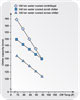
Looking at graph 3, the chiller’s energy usage reduces as the condenser water temperature decreases. At a condenser water temperature of 75°, screw chiller energy usage decreased 18% and centrifugal chiller energy usage decreased 11% as compared to condenser water at 85°.
Conversely, the chiller energy usage increases as the condenser water temperature increases. At a condenser water temperature of 95°, screw-chiller energy usage increased 21%, and centrifugal chiller energy usage increased 19% as compared to condenser water at 85°.
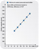
Effect of chilled water temperature difference. The standard chilled water temperature difference is 10°. Looking at graph 4, the chiller capacity increases as the chilled water temperature difference increases. At a chilled water temperature difference of 16°, the scroll and screw chiller capacity increases 2.1% as compared to chilled water difference of 10°.
Conversely, the chiller capacity decreases as the chilled water temperature difference decreases. At a chilled water temperature difference of 6°, the scroll and screw chiller capacity decreases 1.4% as compared to chilled water difference of 10°.
Looking at graph 5, the chiller’s energy usage increases as the chilled water temperature difference increases. At a chilled water temperature difference of 16°, the scroll and screw chiller energy usage increased less than 1% as compared to chilled water difference of 10°.
Conversely, the chiller’s energy usage reduces as the chilled water temperature difference decreases. At a chilled water temperature difference of 6°, chiller energy usage decreased less than 1% as compared to chilled water difference of 10°. This analysis is based on keeping the chilled water supply temperature at 44°.
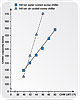
Effect of chilled water leaving temperature. The standard chilled water leaving temperature is 44°. Looking at graph 6, chiller capacity increases as the chilled water leaving temperature increases (graph 4). At a chilled water leaving temperature of 50°, the chiller capacity increased 12.8% for water cooled screw chiller and increased 34.7% for air cooled screw chiller as compared to chilled water leaving temperature of 44°.
Conversely, the chiller capacity decreases as the chilled water leaving temperature decreases. At a chilled water leaving temperature of 40°, the chiller capacity decreased 7.2% for water cooled screw chiller and decreased 19.8% for an air cooled screw chiller as compared to a chilled water leaving temperature of 44°.
Looking at graph 7, chiller energy usage decreases as the chilled water leaving temperature increases. At a chilled water leaving temperature of 50°, the chiller energy usage decreased 12% for the water cooled screw chiller and decreased 10.7% for an air cooled screw chiller, as compared to chilled water leaving temperature of 44°.
Conversely, chiller energy usage increases as the chilled water leaving temperature decreases. At a chilled water leaving temperature of 40°, the chiller’s energy usage increased 13% for the water cooled screw chiller and 8.1% for the air cooled screw chiller as compared to chilled water leaving temperature of 44°.
Summary
This article provided basic chiller component descriptions. It is important to note there are many additional chiller components and subsystems that were not discussed but require careful consideration during the design/selection process. A chiller selection analysis was not included due to site-specific limitations and requirements having a substanital impact on final chiller selection. Chiller selection analysis deserves to be a standalone article. Finally, it is important to understand the affect changing chiller operating parameters from the ARI Standard has on chiller operating performance with the following being noted:- It
is important to use the IPLV for selecting a chiller with the best
energy usage.
- Modifying condenser
water entering temperature has a higher impact on chiller energy than
chiller capacity does.
- Modifying
chilled water leaving/return temperature difference has a higher
impact on chiller capacity than chiller energy usage, when chilled
water leaving temperature remains constant.
- Modifying
chilled water leaving temperature has a substantial impact on chiller
capacity and chiller energy usage. ES

