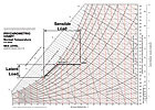
Figure 1.
Psychrometric chart. (Courtesy of Bry-Air, Inc.)
The reasons for controlling rh include prevention of mold growth/condensation, product/artifact life extension, product quality improvement, prevention of moisture re-entrainment, static electricity control, and human comfort. In fact, many of today’s manufacturing processes would not be feasible without dehumidification. This article provides a brief discussion on recommended relative humidities, available dehumidification technologies, moisture load sources, and dehumidification pitfalls that can cause problems with your dehumidification systems.
Recommended Rh
The obvious source for finding recommended rh levels is ASHRAE, however, many other organizations have performed or funded studies on the influence rh has in their particular industries. One study was performed to determine how much weight potatoes lose being stored over time at relative humidities below the optimum storage rh (95%) and the financial impact to the farmer. Other studies have looked at the effect rh has on the storage of archived material (parchment, film, paper). The organizations performing these studies do not always draw the same conclusions for the same application. In light of this fact, the following recommended relative humidities (Table 1), with corresponding temperatures, should be viewed as being general in nature. It is strongly suggested that the design professional research available studies and consult industry experts to determine the best rh for their specific situation.
Figure 2. Solid
desiccant wheel schematic. (Courtesy of Munters Dehumidification Division.)
Dehumidification Technologies
Dehumidifying air can be achieved by utilizing technologies that take advantage of particular air properties. The moisture can be squeezed out, chilled out, adsorbed out, absorbed out, or a combination of these technologies. A description on how each technology dehumidifies, and its limitations, follows.Squeezed out.The higher the air pressure, the less moisture air can retain. A good example is an air compressor. When air is compressed from atmospheric to 100 psig in an air compressor, water condenses out in the air receiver and is removed by a drain valve. Compression is not a very efficient method of moisture removal and will not be discussed further.
Chilled out.The lower the air temperature, the less moisture air can retain. Moisture can be removed from the air by cooling it below its dewpoint temperature. For example, if air entering a cooling coil is 80°F, 50% rh, the air would need to be cooled below its dewpoint of 60.5° in order to start removing moisture from the airstream (Figure 1). Cooling coils have the capability to provide adequate dehumidification for most applications with a dewpoint requirement of 38° or higher. Cooling coils can be DX, chilled water, or glycol/brine water type. The limitations of each coil type are as follows.
- DX coil – Refrigerant coils can cool air to extremely low temperatures, but cooling the air below 32° would cause ice/frost to freeze on the coil, clogging it. Also, the refrigerant expansion within the coil is not necessarily uniform, resulting in an uneven temperature gradient across the coil. To prevent potential frost/ice build-up on the DX coil, the lowest leaving air temperature should be 38° to 40°
- Chilled water coil – Chilled water coils are typically served by a central chilled water system, which supplies chilled water at 40° to 45°. The water/air coil approach temperature is typically 3° to 5°, resulting in a minimum leaving air temperature of 45° to 50° .
- Brine/glycol coil – Brine/glycol coils are typically served by a dedicated chilled water system to serve that specific coil or group of coils. A brine/glycol-chilled water system can supply water at very low temperatures. As with the DX coil, lowering the air temperature below 32° will cause ice/frost build-up on the coil. However, the advantage of the brine/glycol coil over the DX coil is the brine/glycol coil has an even temperature gradient across the coil, making it possible to have a leaving air temperature of 35° without developing ice/frost on the coil.
It is important to note that low dewpoint applications will use purged air that takes low dewpoint process air and uses it for regeneration. The typical adsorption desiccant system consists of a wheel impregnated with the desiccant. The wheel rotates and the airstream passes through the wheel, removing the moisture from the airstream. The wheel rotates into a regeneration section where heated air is blown across the wheel to remove the moisture (Figure 2). The advantage of the adsorption desiccant system is the wheel will not sustain moisture overload when turned off. Due to the adsorption type desiccant system having simpler operation and maintenance, it is the most popularly used desiccant system.
Absorbed out.The other type of desiccant is an absorbent. Absorbents can be solids or liquids, and undergo a chemical change as they absorb moisture. Two chemicals frequently used in desiccant absorption type dehumidifiers are lithium chloride and sodium chloride. Of the two absorption desiccants, lithium chloride is utilized the most. Lithium chloride systems can provide good performance for dewpoints down to -20° and typically use 10% less energy than silica gel adsorption systems. Absorption dehumidifiers come in liquid or solid types with a description of each type as follows:
- Liquid type – The liquid type has the conditioner where the air flows up through packing while the liquid desiccant is sprayed down on the packing. The lithium chloride will absorb the moisture out of the air and drop to a sump at the bottom of the conditioner (Figure 3). The moisture laden lithium chloride is pumped to a regenerator where it is heated and the moisture is removed. Once the moisture is removed, the lithium chloride returns to the conditioner, cooled and ready to absorb more moisture, repeating the cycle. The liquid system’s disadvantages are potential corrosion from lithium chloride carryover in the air supply system and higher maintenance costs. In recent years, technological advancements have reduced the potential of lithium chloride carryover.
- Dry type – Like the adsorption units, the absorption units have a rotating wheel configuration. Unlike the adsorption type desiccant wheels, care must be taken when the absorption desiccant wheel is running. If process or reactivation air is allowed to run through the desiccant wheel without the reactivation heater enabled, the desiccant wheel can be damaged. Controls to prevent this from occurring are standard for this type of equipment.
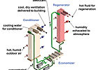
Figure 3. Liquid
desiccant system schematic. (Courtesy of AIL Research, Inc.)
Moisture Load Sources
Moisture load calculations are important in determining how much moisture must be removed in order to maintain the specified space humidity conditions. Take caution when performing these calculations, as moisture sources are not always obvious.A fictitious manufacturing building will serve as a case example for individual moisture source order of magnitude loads. The example is as follows.
- The building is 100- x 500- x 50-ft high with a 100- x 300-ft conditioned area.
- The walls are 8-in. concrete masonry units (CMU) with no vapor barrier, the floors are 6 in. concrete with no vapor barrier, and the roof is built-up over metal decking.
- Each of the seven main doors (3 ft x 7 ft) open one minute per hour.
- One overhead door (10 ft x 16 ft), between conditioned and unconditioned space, is open one minute per hour.
- The outside air is 93° db, 80° mean wb, 135 grains/lb air, 75.5° dewpoint, and vapor pressure (VP) is 0.875.
- Inside air is 75° db, 20% rh, 26 grains/lb air, 32° dewpoint, VP is 0.180.
- An outside wind speed of 15 mph is assumed.
- Seven people work in the conditioned space: two sitting at desk, and five performing light work.
- Manufacturing material is plastic with a process through-put of 10,000 lb/hr.
- The manufacturing floor is washed down in 300 sq ft areas every hour with 100° hot water. Fans are used to shorten the evaporation time and flow parallel to floor at 300 fpm.
- The manufacturing process produces 100 cu ft of unvented natural gas per hour.
- There are no air openings except the doors.
- 15,000 cfm of outside air is brought into the building to provide positive space pressurization.
- Permeation moisture – Building walls and floors typically allow moisture migration from the higher vapor pressure to the lower vapor pressure environment, even when vapor barriers are used. The variables affecting permeation moisture load are material of construction permeance, wall and floor square footage, and vapor pressure differential across material of construction. Looking at the example, the building wall moisture load is 9.5 lb/hr with no vapor barrier. Though 9.5 lb/hr is not a substantial portion of the total space moisture load, it can be significant enough to cause problems. Painting the CMU blocks with a vapor retardant paint will reduce the wall moisture load by 84% to 1.50 lb/hr.
- Product and packaging – Most materials are hygroscopic (affinity to absorb moisture). When a moisture-containing material is placed in an environment having a lower rh, it will de-sorb its moisture into the environment. In our examples, the outside air has an rh of 55% with the inside having a 20% rh. The variables affecting product/packaging moisture load are product moisture content, product entry weight, product de-sorption rate, and rh differential. Looking at the example, the product moisture load is 500 lb/hr. It is important to know the anticipated maximum process material through-put. It might be necessary to pre-dry the material before bringing it into the facility.
- Personnel – Human beings give off moisture through breathing and perspiration. The variables affecting personnel moisture load are space temperature, level of physical activity, and number of people. Looking at the example, the manufacturing building has a personnel moisture load of 2.7 lb/hr. Though the personnel load is low in this example, it can be a major moisture load contributor in high occupation density areas like schools, arenas, and airports.
- Combustion – One of the byproducts of combustion is water vapor. Looking at our example, the manufacturing combustion moisture load is 9.3 lb/hr. Make sure you take into account any combustion moisture removed from the space by an exhaust stack.
- Wet surface evaporation – Any wet surface exposed directly to the environment will evaporate, adding to the moisture load. The variables affecting wet surface moisture load are wet surface area, vapor pressure at water temperature, vapor pressure at air temperature, and air velocity and direction blowing on the water. Water that is 50° with no air movement will take longer to evaporate than water that is 140° with transverse air velocity of 300 fpm. Looking at the example, the water surface evaporation moisture load is 115.5 lb/hr.
- Air infiltration – The amount of air infiltration a building will experience is based upon material of construction, quality of construction, building surface to area ratio, and average wind speed. Buildings tend to have substantial leakage through door cracks, doors opening and closing, wall seams/joints/cracks, wall penetrations, and any other crack that will allow moisture laden air to leak into the building. The variables affecting air infiltration are hole opening area, air velocity through opening, air density, and moisture differential between outside and inside air. Looking at the example, air leakage coming into the building is reduced due to positive air pressurization within the building. However, there will be air leakage when doors are opened and closed. The resulting air leakage moisture load is 149.1 lb/hr. If the personnel doors have air locks installed, the air leakage is reduced to 10.6 lb/hr, a 93% reduction in moisture load.
- Ventilation – Most buildings will bring in outside air to replace exhausted air, maintain IAQ, and provide building pressurization. Providing enough ventilation to positively pressurize the building will reduce uncontrolled air leakage into the building. Looking at the example, the ventilation moisture load is 976.6 lb/hr. Ventilation moisture loads tend to be one of the highest moisture loads that need to be mitigated.
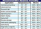
Table 1. Recommended
rh levels for typical applications.
Dehumidification Pitfalls
It is more difficult to maintain a specific rh than a specific temperature, resulting in it being easier to lose humidity control. The following are specific problems that need to be understood and accounted for.Wrong calculations.When performing cooling load calculations, it is typical to use the 0.4% design condition drybulb temperature with mean coincident wetbulb temperature. By using this weather data, are we assured the maximum total and latent load is calculated? The answer is no. There is a good probability that a warm, rainy afternoon will produce a substantially higher latent and total cooling load. The result will be that the system will not be able to maintain the space design rh. It is important to calculate the cooling load at the maximum outside air dewpoint temperature with coincident drybulb temperature.ASHRAE Handbook – Fundamentalsprovides the maximum outside air dewpoint temperature with coincident drybulb temperature.
Wheel temperature rating. Do you know the maximum temperature rating for the desiccant wheel you are using? How is the desiccant wheel being regenerated (steam/natural gas)? Is there a potential the desiccant wheel will be overheated, and what damage would result? An overheated desiccant wheel can warp or deform, requiring replacement.
Space pressurization. As noted above, reducing moist air infiltration into a controlled space to a minimum is necessary to provide adequate rh control. Spaces having neutral or negative space pressurization in relation to surrounding spaces and/or outside environment will be very difficult to maintain at a set rh, especially spaces requiring very low rh.
Building envelope integrity. Reducing moisture migration through building walls and floors to a minimum is necessary to provide adequate rh control. Some facilities cannot maintain a set rh due to walls and floors having high permeance rates. Also, reducing uncontrolled moisture migration through cracks and around penetrations is extremely important. Sealing is a good deal.
Humidification operation. Is your humidifier operation locked out during dehumidification operation? Does your humidifier have a two-position valve as well as a modulating valve to prevent humidifier leakage?
Final Thoughts
A properly designed facility, both architecturally and mechanically, can provide a stable rh environment. This article tried to give an appreciation for the complex variables that affect dehumidification design and operation. Going forward, do the following steps:- Know the required temperature and rh set points, including allowable humidity rate of change.
- Know the architectural layout and design. Work with the architect to ensure the facility is designed to enable good humidity control.
- Calculate loads at both highest sensible and highest latent load points.
- Select dehumidification technology that provides the best solution for the client in regard to capital cost, operating cost, maintenance cost, and reliability of operation.

