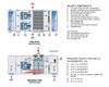
FIGURE 1. This figure shows a recirculation air cooling by evaporation (RACE) unit with an evaporative cooled condenser for the refrigeration final stage of cooling. Dual direct-drive blowthrough fans have been selected for reliability, redundancy, and reduced fan energy losses.
We thought that might get your attention. A wider envelope for ASHRAE-recommended conditions, attention to traditional topics like air contamination and water treatment, and work on new technology all offer opportunities for teams willing to expand their horizons. You might be surprised at some of the cities best poised to take advantage of today’s circumstances.
The ASHRAE Technical Committee, TC-9.9 Mission Critical Facilities, has worked hard to reduce the energy consumed in cooling the electronics in data centers. In 2008, the “Environmental Guidelines for Datacom Equipment” was expanded to include ASHRAE Class I and II facilities in an effort to reduce refrigeration cooling loads.
The new recommended inlet air conditions in the cold aisle have been established as 18°C (64.4°F) to 27°C (80.6°F) for entering air temperature and 5.5°C (41.9°F) to 15°C (59°F) dewpoint for absolute moisture content. The cold aisle relative humidity (rh) high limit is set at 60%. IT manufacturers have determined that exceeding these limits for short periods would not result in a equipment failure but running within this envelope will extend equipment life and increase reliability.1
Increasing the size of the envelope for inlet air temperature and humidity limits greatly expands the annual hours that data centers may make use of the free cooling offered by wetbulb (wb) and airside economizer cycles.2Both these systems use outdoor air to develop the required cold aisle inlet delivery conditions when Mother Nature cooperates.
Still, data center operators are very reluctant to introduce outdoor air into their computer equipment environments. This reticence is based on the prejudice that particulate and gaseous contaminants in polluted outdoor air will compromise their mission critical environment. For years, computer room air conditioning (CRAC) units that recirculate the hot aisle return air have been the basis of efforts to reduce and control both filtration and humidification requirements within the space.
Cooling and Contamination Control
New technology in the field of air-to-air indirect (dry) evaporative cooling (IEC) heat exchangers, coupled with the newly expanded ASHRAE cold aisle requirements, can answer these data center cooling concerns. A recirculation air conditioning by evaporation (RACE) unit with a cooling energy efficiency ratio (EER) above 50 is illustrated in Figure 1.The heart of this central station air handler is a polymer air-to-air indirect evaporative cooling heat exchanger, shown in Figure 2. Hot aisle return air is pushed through the inside of the horizontal tubes and is sensibly cooled by a “scavenger” ambient airstream drawn upward across the wetted exterior surface of the tubes. Sufficient surface is provided to yield a 70% approach of the 100° hot aisle return air temperature to the ambient wetbulb (wb) condition of the outdoor air. The dry-side static pressure penalty for this dry cooling device is in the range of 0.5 to 0.8 in. w.g. Wetside pressure losses are in the range of 0.8 to 1.3 in. w.g.3
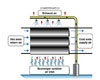
FIGURE 2. The first stage of sensible cooling is provided by the EPX polymer tube air-to-heat exchanger using ambinet wb temperatures for heat rejection through indirect evaporative cooling.
Only 5.4 tons of cooling remain to be provided by the direct expansion (DX) onboard refrigeration system. Rather than rejecting the heat of compression to a condenser coil on the roof where ambient drybulb (db) temperatures are 97° or higher, the condenser coil is located in the humid but cool 79.4° airstream off the sprayed IEC heat exchanger.
Almost like an evaporative cooled condenser heat rejection design, this system will have EERs in the range of 12 to 15 when refrigeration is required during high ambient humidity conditions. Unlike the evaporative-cooled condenser design, water treatment problems are not a concern, since the finned condenser coil remains dry. In addition to higher EERs, the benefits of this onboard DX design include higher compressor capacity at a lower refrigeration condensing temperature and increased compressor life due to the reduced temperature lift.4
A quick calculation indicates that, with a 70% wb depression efficiency, this RACE heat exchanger will produce all the cooling required at ambient wb temperatures below 64° when return air hot aisle temperatures are assumed to be 100° db.
Using typical meteorological year (TMY 2) weather data developed by National Renewable Energy Laboratories (NREL) in Golden, CO, Figure 4 shows the number of hours per year that refrigeration could be eliminated for a 24/7/365 duty cycle in 35 cities throughout the U.S. During these hours, this IEC heat exchanger may provide a 75° cold aisle supply condition. The right side of Figure 4 shows the percent of mechanical cooling reduction, assuming a 2° fan heat addition, at the 0.4% ASHRAE wb design.
Since ambient db design temperatures always coincide with a lower wb condition, the cooling capacity of the heat exchanger is higher at the db design and the residual cooling tons left to refrigeration are lower. Like a cooling tower, the wb design is the critical design criteria for a RACE unit.
A NEW INDIRECT EVAPORATIVE COOLING HEAT EXCHANGER
Figure 2 shows the construction of a new IEC air-to-air heat exchanger. Polymer airfoil-shaped tubes are used to minimize air-side static pressure parasitic losses on the wetside of the tubes. The polymer material meets Underwriters Laboratories (UL) Standard 94V-0 flame spread. The heat exchanger has been tested and is compliant with UL900 Class II. Compliance with these standards is essential, since the heat exchanger is located within the building supply air duct system. A unique sealing method bonds the tubes to the tube-sheet, preventing water leakage from the wetside of the heat exchanger to the recirculated airflow on the dry side.Hard water and high temperature differences require a robust air-to-air heat exchanger that can shed mineral deposits caused by the indirect evaporative cooling process. The wb depression across the tubes (Figure 2) ranges from only 20° in humid climates to more than 40° in more arid climates. Water evaporation rates are consistent with that of cooling towers with comparable heat of rejection. Required bleed rates for the spray water recirculation sump are a function of the evaporation rate and the water chemistry of the makeup water at the site. For most potable makeup water systems, a bleed rate equal to the evaporation rate will maintain sump dissolved solids at an acceptable level.
A 2002 installation of this IEC module, located in Death Valley, CA, has been monitored for water hardness contamination of the wet side of the polymer tubes. Total dissolved solids (TDS) in Death Valley potable water range from 240 to 19,104 mg/L with an average of about 1,940 mg/L. At that site in October of 2005, it was discovered during a job visit that flexing of the polymer tubes during fan startup and shut down has effectively worked to shed water hardness deposits into the sump. This self-cleaning feature of this heat exchanger extends life expectancy, particularly in extreme hard water environments.5
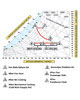
FIGURE 3. The heat rejection process is plotted on a psychrometric chart for the Sacramento, CA, ASHRAE 0.4% wb design condition.
WATER TREATMENT
For a mission critical application such as a data center, the cooling system water treatment should be sustainable and fail safe. A new, non-chemical, water treatment that uses a pulse-power technology is recommended for the IEC sump recirculation water.6Originally developed for cold pasteurization in the food industry, this system encapsulates water hardness minerals and particles into a non-adherent powder that is harmlessly deposited in the bottom of the sump. The device controls scaling of the wetted heat exchanger tubes and biological growth in the sump water. Under proper operation, the pulse-power component will maintain clean sump water with low bacteria counts free of bio-film and eliminate the breeding ground for the amplification ofLegionellaand other waterborne pathogens.7
For multiple roof-mounted IEC units, a central sump may be designed to accumulate the spray water. One central sump reduces pumping energy. A single set of dual pumps, for redundancy, replaces the recirculation pump at each unit on the roof. A variable volume pump would maintain the required system head pressure in response to a demand at each unit for spray water to wet the IEC heat exchanger. Water treatment costs are reduced, and the weight of the sump water at each roof-mounted unit is eliminated. The total blow down water consumption for the evaporative cooled system is reduced, thereby reducing the demand for potable makeup water. The central sump may also be used as a gray water reservoir for flushing toilets and landscape irrigation, since the water treatment system does not add any chemicals.
EER CALCULATION FOR SACRAMENTO
EER is defined as the cooling energy delivered in Btuh divided by the Watts (W) of electrical energy consumed to produce the cooling effect. For the Sacramento example of a 10,000 cfm cooling design in Figure 3, the parasitic losses for the IEC heat exchanger consist of the following:| Energy to push the air through the dry side of the IEC | = 1,350 W |
| Energy to pull the air through the wet side of the IEC | = 2,170 W |
| Spray water recirculation pump energy | = 750 W |
| Total energy consumed | = 4,270 W |
The sensible cooling produced by the IEC at the 0.4% ASHRAE wb design condition is equal to 231,000 Btuh, therefore the EER calculates to be 54.1.
The refrigeration portion of the sensible cooling effect required to reach the 75° cold aisle delivery temperature is calculated to be 66,000 Btuh for the 10,000 cfm. The compressor energy input is 3,850 W, and the fan energy required to overcome the condenser coil static pressure loss is calculated to be 870 W. The mechanical cooling EER calculates to be 14.
The overall cooling EER for both IEC and refrigeration cooling pencils out to be 33. Compare this to a conventional CRAC system rejecting data center heat, on the ASHRAE 0.4% db design day, with an air cooled refrigeration design at an EER of only 10 to 12.
During winter operation, when the air-to-air heat exchanger operates without the spray pump energy loss, the EER increases to 67.6. Operating speed for the VFD on the outdoor air fan is reduced at low wb ambient conditions and lower db temperatures saving fan energy during cold weather.
COLD-AISLE TEMPERATURE CONTROL
Since data center cooling systems are essentially constant volume, close control of the cold aisle supply air temperature is essential. With a recirculation air design and sensible cooling of the supply air, room dewpoint conditions will not change except through moisture migration in or out of the space.During warm ambient conditions, where the air db temperatures are above 45°, the water recirculation pump and sprays will be on to wet the scavenger air side of the heat exchanger (Figures 1 and 2). The scavenger air fan VFD will control the mass flow of air on the wet side of the heat exchanger to maintain the 75° db supply air set point to the cold aisle.
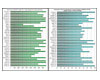
FIGURE 4. Using TMY2 hour-by-hour weather data, these two bar charts show, for various U.S. cities, the number of hours per year (left) where mechanical cooling may be eliminated and the percentage reduction (right) of mechanical cooling at the ASHRAE 0.4% wb design condition.
Refrigeration EERs for the DX cooling stage are a function of the local design ambient wb condition at the coincident db temperature. The more arid the local climate, the higher will be the refrigeration EERs, since there will be a greater drop in the ambient air db temperature within the wet side of the air-to-air heat exchanger upstream of the refrigeration condenser coil. Figure 1 shows that Sacramento, would provide a 17.6° reduction in the ambient db temperature in which to reject the refrigeration heat of compression.
At ambient db conditions below 45°, the water sprays and recirculation pump would not be required to reject the data center heat. With a 50% dry-to-dry heat transfer effectiveness, the scavenger air fan would again modulate the scavenger air across the heat exchanger at a mass flow sufficient to maintain the 75° cold aisle delivery temperature. Below 40° ambient db temperatures, the sump would be drained to protect against freezing.
Data center architecture is critical to the successful application of the cold aisle airflow to the inlet of the electronics being cooled. Unfortunately, this design detail is often outside the province of the mechanical consultant engineer. Without effective separation of the hot aisle and cold aisle airflow paths, a data center is condemned to furnishing lower supply air temperatures and higher airflow rates. Data center design professionals need to work together closely to ensure that hot aisle air is not recirculated to the inlet of the electronics and that cold aisle air is not short-circuited to the hot aisle without passing through the electronics being cooled.
SPACE PRESSURE AND HUMIDITY CONTROL
A positive room pressure is required within the data center to reduce infiltration of outdoor air. A separate AHU that would introduce, filter, and condition the outdoor air is indicated for this task. When ambient humidity levels are below the Class I and Class II data center minimum dewpoint condition of 41.9°, the outdoor air must be humidified. When outdoor air dewpoints are above the 59° maximum, the outdoor air introduced needs to be dehumidified.In cold climates where there are many annual hours of cold, dry outdoor air conditions to deal with, a unit with an adiabatic direct evaporative cooling/humidifying component should be considered. Because data centers generate so much heat, a 12-in.-deep wetted media pad selected at 400 fpm face velocity will provide free humidification and additional data center heat rejection.8
PARTICULATE AND GASEOUS CONTAMINATION
The introduction of outdoor air for data center cooling with an air economizer saves cooling energy but increases exposure of the electronic equipment to contamination, corrosion, and humidity excursions. A recentASHRAE Transactionspaper discussed the effect of corrosive particulate and gases on computer reliability.9The paper points out that dust that settles on printed circuit boards can lead to short circuiting in the presence of ambient moisture (humidity). The electrical shorting occurs when ionic bridges are created by the dust particles accelerated by moisture from the environment.
The most important parameter controlling corrosion and short circuiting is the relative humidity at the inlet to the electronics. Research by the authors indicates that corrosion becomes negligible below 50% relative humidity. Data centers with airside economizers require real-time monitoring of the outdoor air. In the event of a sudden rise in the level of dust or gaseous contaminant in the outdoor air, the system should close off the external air source and revert back to a recirculation mode.
SUMMARY
Figure 4 summarizes the data center cooling impact of the RACE design in 35 cities throughout the 50 states of the U.S. Humid climates such as Honolulu, Tampa, and New Orleans have the lowest percentage of annual hours where refrigeration may be eliminated. Surprisingly, these same cities, at the ASHRAE 0.4% wb design condition, would yield a better than 50% reduction in refrigeration tons required to delivery 75° to the cold aisle.Northern, Western, and higher elevation locations show the greatest promise of energy savings. Cities where mechanical cooling is eliminated and where the onboard refrigeration system could serve as a backup include Anchorage, Colorado Springs, Helena, Reno, Redmond, Casper, and Cheyenne.
RACE units ensure the integrity of the electronic equipment by controlling data center dewpoint and limiting external contamination while offering a very efficient method of heat rejection.ES
REFERENCES
1. “Best Practices for Datacom Facilities Energy Efficiency,” ASHRAE Datacom Series, Table 2.1, 2008: 19.2. Scofield, C.M. and Weaver, T.S., “Using Wet-Bulb Economizers: Data Center Cooling,”ASHRAE Journal, August 2008: 52.
3.2008 ASHRAE Handbook - Systems and Equipment, Chapter 40, “Evaporative Air-Cooling Equipment,” Figure 3, pg. 40.3.
4. Op.cit
5. Scofield, M. and DesChamps, N., “Death Valley: The Ultimate Test for Evaporative Cooling,”HPAC Engineering, July 2006: 40.
6. ASHRAE,ASHRAE Green Guide: The Design, Construction and Operation of Sustainable Buildings, ASHRAE Green Tip 14, 2nd Ed., pg. 191.
7. Puckorius, P.R., et al, “Why Evaporative Coolers have not caused Legionnaire’s Disease,”ASHRAE Journal 37(1), 1955:29-33.
8. Op.cit
9. Singh, Petal, “Particulate and Gaseous Contamination: Effect on Computer Reliability and Monitoring”, ASHRAE Transaction Paper CH-09-008, 2009.


